
Gimbal-less micro-electro-mechanical-system tip-tilt and tip-tilt-piston actuators and a method for forming the same

a micro-electromechanical system and actuator technology, applied in the direction of instruments, optical elements, optical waveguide light guides, etc., can solve the problems of increasing complexity and cost, complex fabrication, and increasing the number of deposition and cmp steps

Active Publication Date: 2008-03-13
ADRIATIC RES INST
View PDF17 Cites 32 Cited by
  • Summary
  • Abstract
  • Description
  • Claims
  • Application Information

AI Technical Summary

Benefits of technology

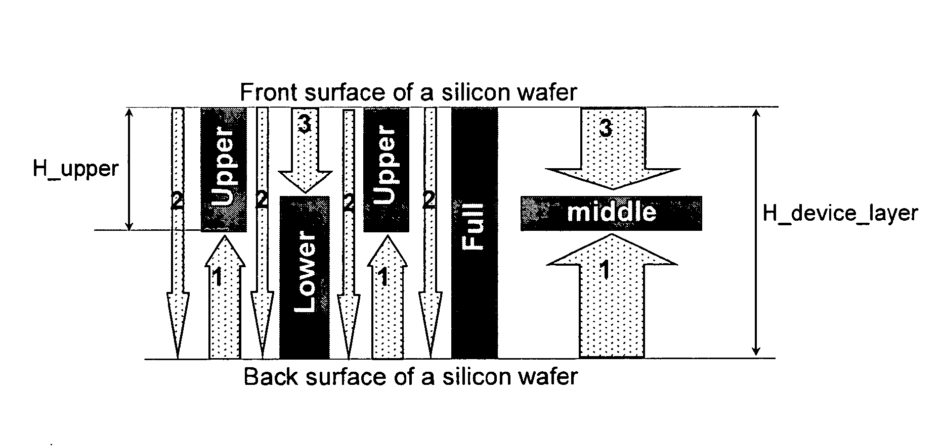
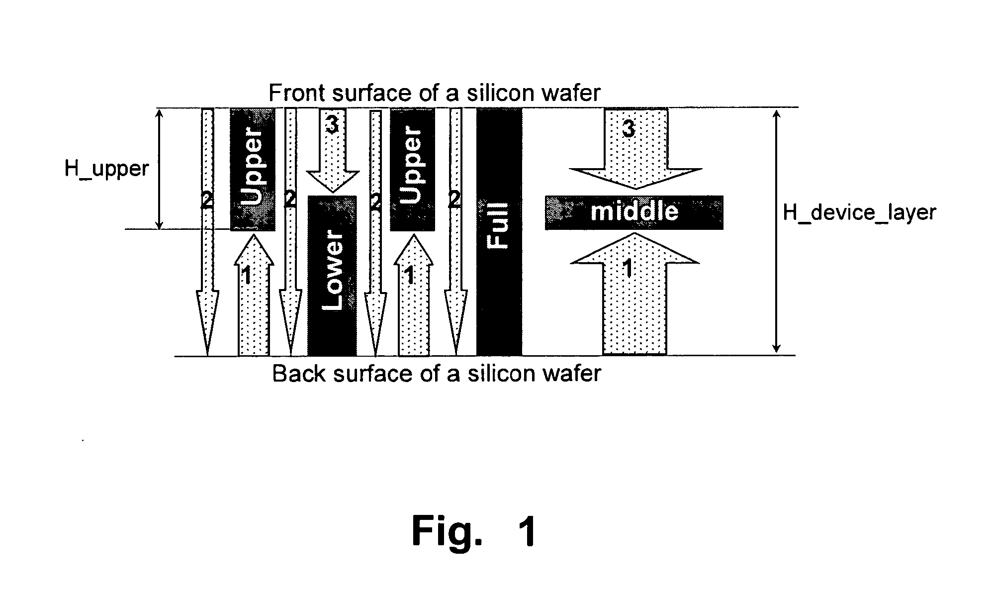
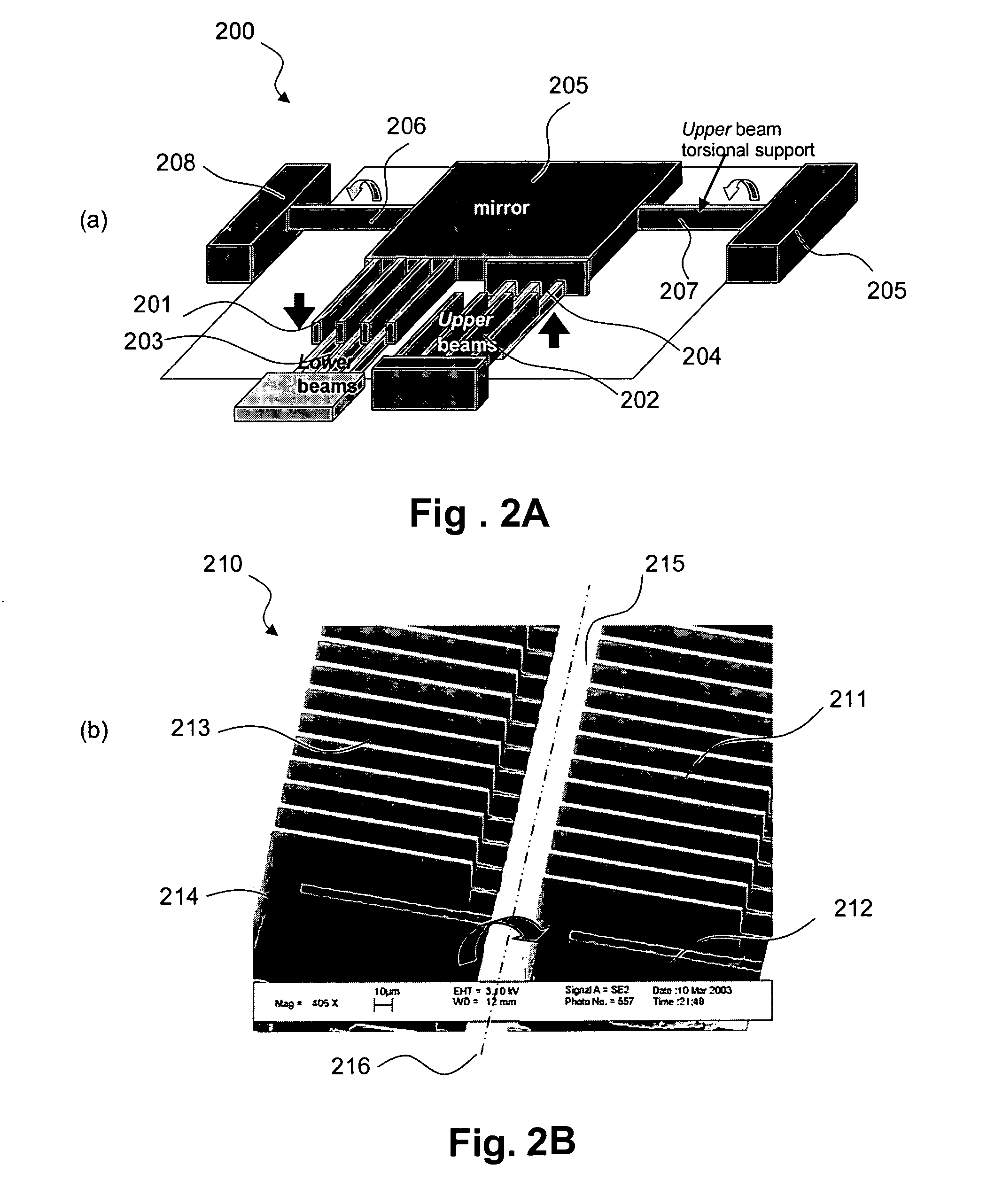
The invention is about micro-electro-mechanical system (MEMS) devices and methods for their fabrication. The invention includes a device mount that is supported by two or more bi-axial linkages mechanically coupled between the device mount and an actuator. The bi-axial linkages provide the device mount with two or more degrees of movement. The invention also includes one or more actuators arranged in a pattern that one end of each actuator abuts a side of a neighboring actuator proximate the device mount and another end of each actuator extends away from the device mount without abutting a neighboring actuator. The invention also includes methods for fabricating a micro-electro-mechanical system (MEMS) by preparing a substrate, etching the substrate to form beams, and patterning the substrate with a photoresist or oxide mask. The substrate may be bonded to form a bonded substrate with the etched surface of the upper layer facing a polished surface of the lower layer. The technical effects of the invention include improved device mount stability, reduced actuator interference, and improved device performance.

Problems solved by technology

However, the additional deposition and CMP steps significantly increase complexity and cost.
In all cases, complex fabrication has been required, and relatively low frequencies have been achieved due to the gimbals' slow outer axis.
In applications where high speed static scanning is required the previous methods do not provide adequate solutions.

Method used


Image

  • Gimbal-less micro-electro-mechanical-system tip-tilt and tip-tilt-piston actuators and a method for forming the same
  • Gimbal-less micro-electro-mechanical-system tip-tilt and tip-tilt-piston actuators and a method for forming the same
  • Gimbal-less micro-electro-mechanical-system tip-tilt and tip-tilt-piston actuators and a method for forming the same

Examples


Embodiment Construction

[0055] Embodiments of the present invention utilize a combination of one-axis vertical comb-drive based rotation actuators and bi-axial mechanical linkages that allow 2DoF of rotation (tip-tilt,) or 3DoF of motion (tip-tilt-piston) for a central structural support for an optical element such as a micromirror. The comb-drive actuators can by themselves achieve >20° of static optical deflection at frequencies of up to several kHz (with a 600 μm diameter and 30 μm thick silicon micromirror attached to the support). Such a configuration can effectively decouple the problem of two-axis scanners and can independently optimize and approach the problem of improving one-axis rotators, as well as the linkages that form the overall 2DoF structure. While many embodiments described herein use comb-drive rotators to produce the actuation of the central support, the design can also utilize pure vertical actuators, gap-closing electrodes or piston actuators.

[0056] In order to achieve the goal of l...


PUM

PropertyMeasurementUnit
Degree of Freedomaaaaaaaaaa
diameteraaaaaaaaaa
diameteraaaaaaaaaa

Abstract

Fully monolithic gimbal-less micro-electro-mechanical-system (MEMS) devices with large static optical beam deflection and fabrications methods are disclosed. The devices can achieve high speed of operation for both axes. Actuators are connected to a device, or device mount by linkages that allow static two-axis rotation in addition to pistoning without the need for gimbals, or specialized isolation technologies. The device may be actuated by vertical comb-drive actuators, which are coupled by bi-axial flexures to a central micromirror or device mount. Devices may be fabricated by etching an upper layer both from the top side and from the bottom side to form beams at different levels. The beams include a plurality of lower beams, a plurality of full-thickness beams, and a plurality of upper beams, the lower, full-thickness and upper beams That form vertical combdrive actuators, suspension beams, flexures, and a device mount.

Description

CROSS-REFERENCE TO RELATED APPLICATION [0001] This application is a divisional of prior US patent application Ser. No. 11 / 003,271 filed Dec. 2, 2004, the entire disclosures of which are incorporated herein by reference. [0002] This application claims the benefit of prior U.S. provisional application No. 60 / 526,510 filed Dec. 2, 2003, the entire disclosures of which are incorporated herein by reference.FIELD OF THE INVENTION [0002] Embodiments of the present invention relate to micro-electro-mechanical-system (MEMS) two-dimensional (tip-tilt) actuator or a three dimensional (tip-tilt-piston) actuator with articulated suspension structures for high fill factor arrays. BACKGROUND OF THE INVENTION [0003] A MEMS (Micro-Electro-Mechanical-System) device is a micro-sized mechanical structure having electrical circuitry fabricated together with the device by various microfabrication processes mostly derived from integrated circuit fabrication methods. The developments in the field of microe...

Claims


Application Information

Patent Timeline
Patent Type & Authority Applications(United States)
IPC IPC(8): H01L21/461C23F1/00H01L21/302
CPCG02B26/0841B81B3/0062
Inventor MILANOVIC, VELJKOMATUS, GABRIEL A.
Owner ADRIATIC RES INST
Learn More