
Method and apparatus for medical imaging using near-infrared optical tomography and flourescence tomography combined with ultrasound

Active Publication Date: 2008-03-06
UNIV OF CONNECTICUT
View PDF10 Cites 39 Cited by
  • Summary
  • Abstract
  • Description
  • Claims
  • Application Information

AI Technical Summary

Benefits of technology

[0007] Diffusive optical tomography and fluorescent diffusive optical tomography individually provide benefits over alternative imaging methods. Each of these imaging methods is confronted with challenges that impede widespread acceptance and implementation. However, a

Problems solved by technology

Although diffusive optical tomography is a promising medical imaging technique, DOT imaging methods and DOT apparatus have yet to yield high quality reconstructions of inclusions due to fundamental issues with intense light scattering.
However, FDOT methods have exhibited less than desirable reconstruction accuracy due to imperfect uptake of the fluorophore and background fluorophore noise.
Each of these imaging methods is confronted with challenges that impede widespread acceptance and implementation.

Method used


Image

  • Method and apparatus for medical imaging using near-infrared optical tomography and flourescence tomography combined with ultrasound
  • Method and apparatus for medical imaging using near-infrared optical tomography and flourescence tomography combined with ultrasound
  • Method and apparatus for medical imaging using near-infrared optical tomography and flourescence tomography combined with ultrasound

Examples


example 1

[0085] A study was conducted wherein a semi-infinite medium was simulated using 0.5% intralipid solution comprising 0.23 μM of a fluorescent dye (e.g., Cy5.5). The solution was disposed in a vessel, and a hollow, transparent cube measuring 0.8×0.8×0.8 cm was filled with the intralipid solution and 5.0 μM of the fluorescent dye (Cy5.5) and submerged in the vessel. The position of the fluorescent cube was controlled using a three dimensionally adjustable micrometer.

[0086] Three tests were then conducted to estimate the fluorescent cubes structural parameters and imaging fluorescence concentration. The first set of measurements was made on the 0.5% Intralipid solution without the fluorescent dye or the cube. This data was considered to be the leakage of excitation light from the collimating system and filter 54. The second set of measurements was made on the solution with the 0.23 μM of a fluorescent dye dissolved therein, without submerging the fluorescent cube. This set of was consi...

example 2

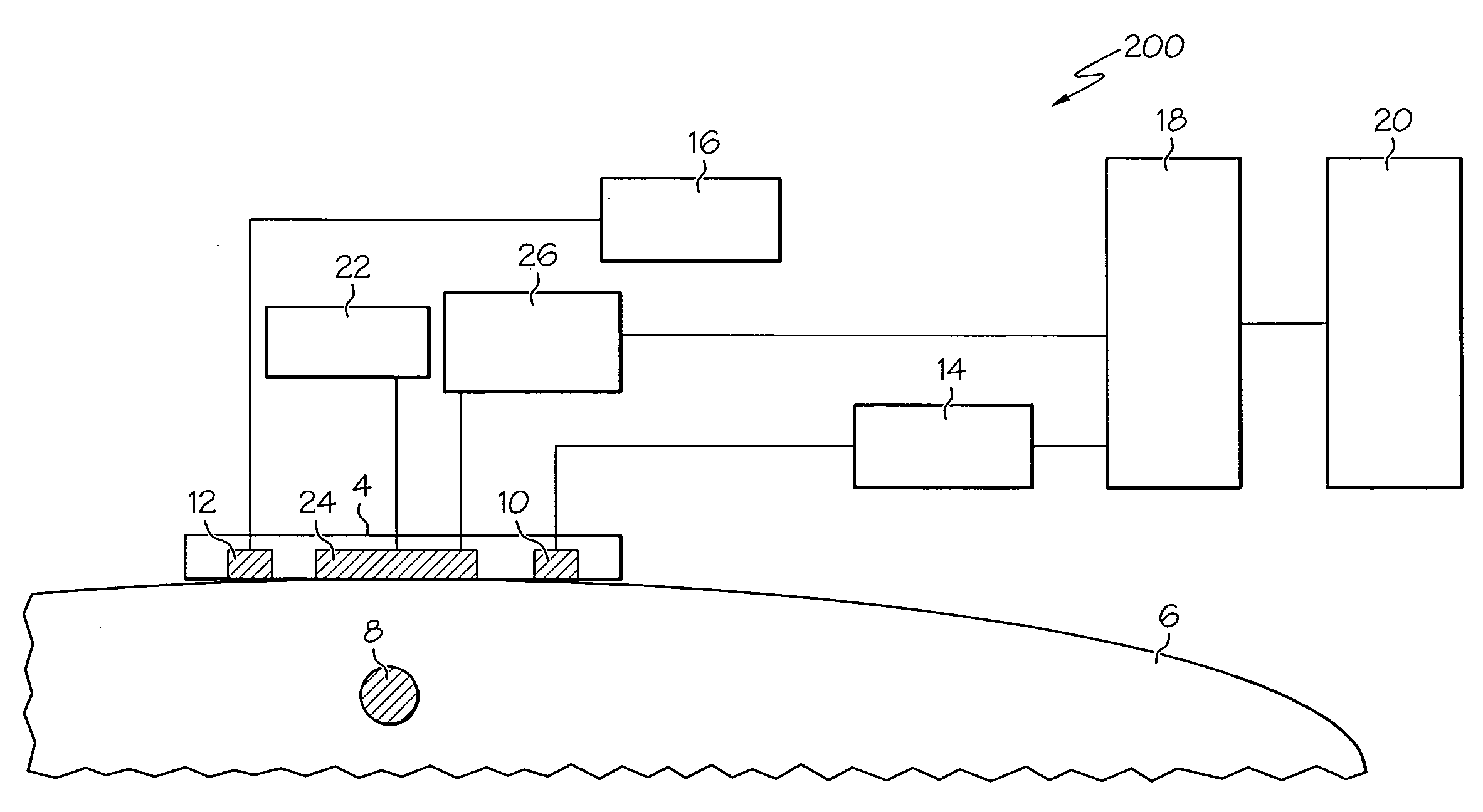
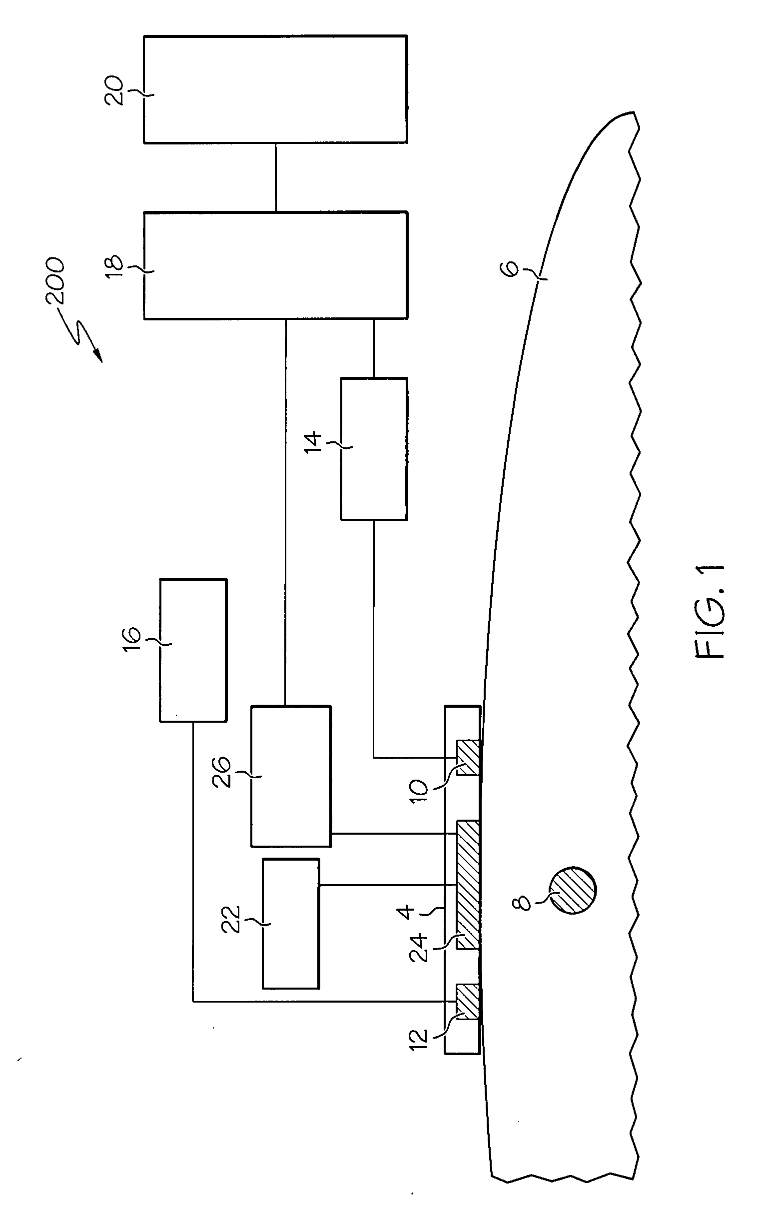
[0095] This example was conducted to test the experimental set-up depicted in the FIG. 15. It also depicts the difference between using the first algorithm and the third algorithm. FIG. 16 shows the reconstructed X-Y position of the target where the target positions X and Y were simultaneously changed, and the target was controlled at a depth of approximately 1.5 cm. The open circles indicate the measured center positions of the target in the X-Y plane and the bars along X and Y directions denote the radius of the target. The solid circles show the estimated positions. In the FIG. 16, the estimated structural parameters of the spherical target are obtained by using optical imaging method to fine-tune the target parameters. The center positions of the spherical target are in the X-Y plane. The error bars indicate the diameters of the spherical target. The first algorithm was used for the estimation.

[0096] The estimated depth and radius are also shown in FIG. 17 and the numbers in pa...


PUM


Abstract

Methods and apparatus for medical imaging using diffusive optical tomography and fluorescent diffusive optical tomography are disclosed. In one embodiment, a method for medical imaging comprises, scanning a tissue volume with near-infrared light to obtain structural parameters, wherein the tissue volume includes a biological entity, scanning the tissue volume with near-infrared light to obtain optical and fluorescence measurements of the scanned volume, segmenting the scanned volume into a first region and a second region, and reconstructing an optical image and a fluorescence image of at least a portion of the scanned volume from the structural parameters and the optical and fluorescence measurements. In another embodiment an apparatus for medical imaging is disclosed.

Description

CROSS-REFERENCE TO RELATED APPLICATIONS [0001] This application claims priority to Provisional Application No. 60 / 806,675 filed Jul. 6, 2006, the entire contents of which are hereby incorporated by reference.STATEMENT OF FEDERALLY FUNDED RESEARCH [0002] This invention was made with support from the United States Government under contract number R01EB002136 awarded by the National Institutes of Health and contract number W81XWH-04-1-0415 awarded by the Department of Defense. The Government has certain rights in the invention.TECHNICAL FIELD [0003] This disclosure relates primarily to the field of biological imaging, particularly to medical imaging. More specifically, to medical imaging equipment and methods for medical imaging using combined near-infrared optical tomography, fluorescent tomography and / or ultrasound. BACKGROUND OF THE INVENTION [0004] Diffusive optical tomography (DOT) is a form of computer-generated tomography wherein near-infrared light (NIR) is directed at a biolog...

Claims


Application Information

Patent Timeline
IPC IPC(8): A61B5/05
CPCA61B5/0091A61B5/4312A61B8/0825G01N21/6428G01N21/1702G01N21/4795A61B8/4416A61B5/0035
Inventor ZHU, QUINGYUAN, BAOHONG
Owner UNIV OF CONNECTICUT
Learn More