Gas laser apparatus, and method and device for monitoring blower

a laser apparatus and blower technology, applied in mechanical apparatus, machines/engines, active medium materials, etc., can solve the problems of affecting the operation of the blower, the quality of the blower is likely to be affected, and the inspection time is likely to be overruled, so as to reduce the burden on the operator, eliminate the risk of erroneous instructions, and establish stable operation for a long time

Inactive Publication Date: 2008-03-06
FANUC LTD
View PDF1 Cites 11 Cited by
  • Summary
  • Abstract
  • Description
  • Claims
  • Application Information

AI Technical Summary

Benefits of technology

[0009]It is an object of the present invention to provide a gas laser apparatus using a gaseous laser medium, which can automatically manage the time when lubricant or lubricating oil in a blower needs to be changed, and can automatically perform an initialization of management data after the lubricant is changed, and thus can significantly reduce burden on an operator so as to effectively eliminate a risk of erroneous instructions, so that the gas laser apparatus can establish stable operation for a long time
[0010]It is another object of the present invention to provide a method and device for monitoring a maintenance state of a blower adapted to be provided in a gas laser apparatus, which can automatically manage the time when lubricant or lubricating oil in a blower needs to be changed, and can automatically perform an initialization of management data after the lubricant is change, and thus can significantly reduce burden on an operator so as to effectively eliminate a risk of erroneous input.

Problems solved by technology

Moreover, the blower of this type is exposed to high temperature when the laser beam is generated, and therefore, a lubricant or lubricating oil, supplied to a bearing section of an impeller, is likely to be degraded in quality.
However, when the maintenance / inspection time of the lubricant is managed manually by an operator, human errors such as oversight of the inspection time may occur.
In this connection, the maintenance-time monitoring device is incorporated into a control section for controlling the exciting and resonating operation of the medium gas in the gas laser apparatus, and therefore, in a state where the gas laser apparatus is de-energized, it is difficult to determine by a predetermined signal, whether the lubricant in the blower has been changed or not.
When the technique for manually inputting the lubricant-change completion signal is adopted, burden on the operator may be increased, erroneous instructions by the operator may happen, and as a result, an unintended reset operation (i.e., initialization of management data) may take place.
Further, when the lubricant in the blower is changed, since an internal space of the medium circuit of the gas laser apparatus is exposed to environmental air, impurities or foreign matter, other than the medium gas, may enter the excitation section or the light resonance section, and as a result, the hermetical feature of the medium circuit may be impaired.
As a result, burden on the operator may be significantly increased, and the frequency of erroneous instructions by the operator may be increased.

Method used


Image

  • Gas laser apparatus, and method and device for monitoring blower
  • Gas laser apparatus, and method and device for monitoring blower
  • Gas laser apparatus, and method and device for monitoring blower

Examples


Embodiment Construction

[0028]The embodiments of the present invention are described below, in detail, with reference to the accompanying drawings. In the drawings, same or similar components are denoted by common reference numerals.

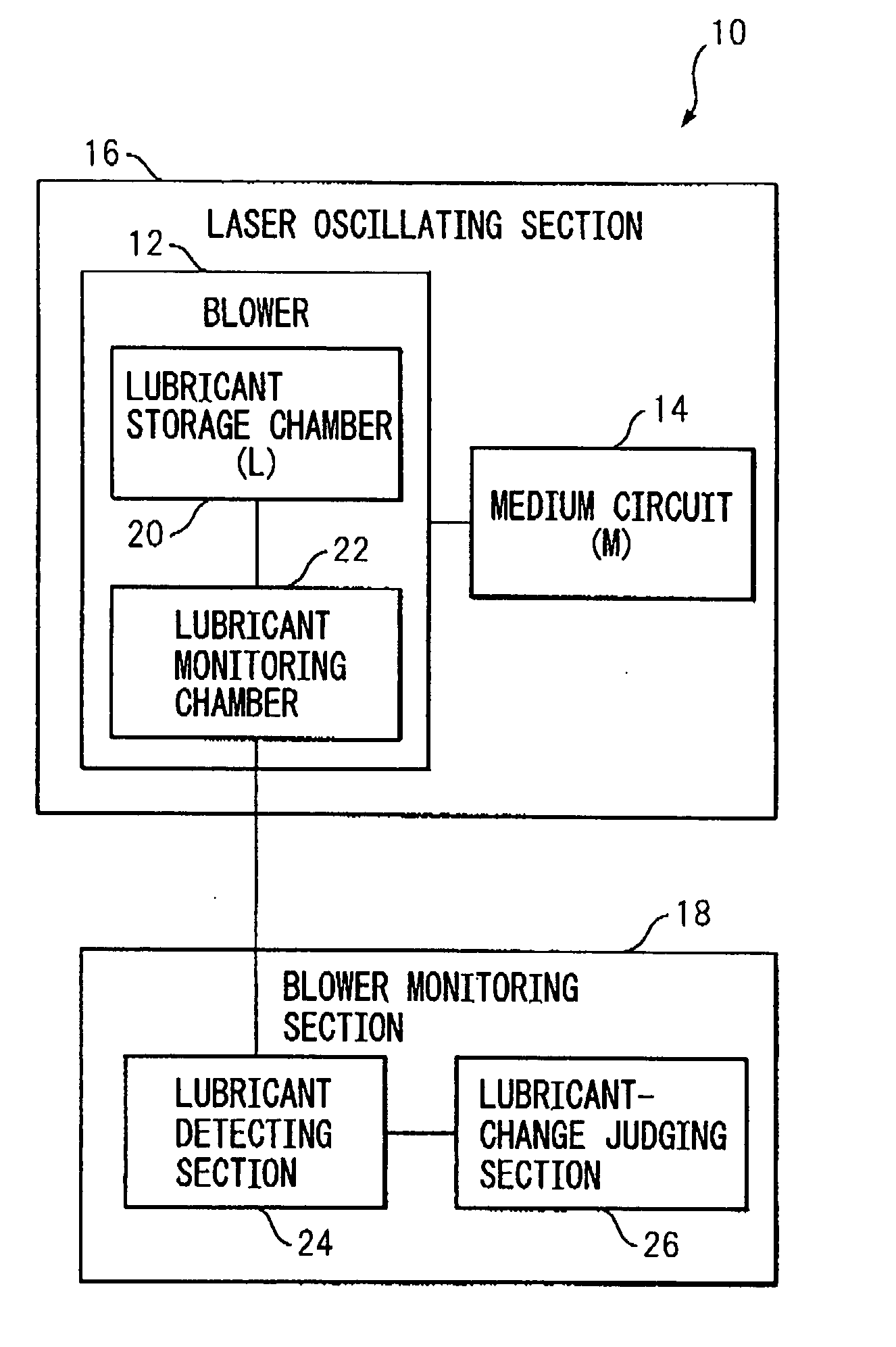
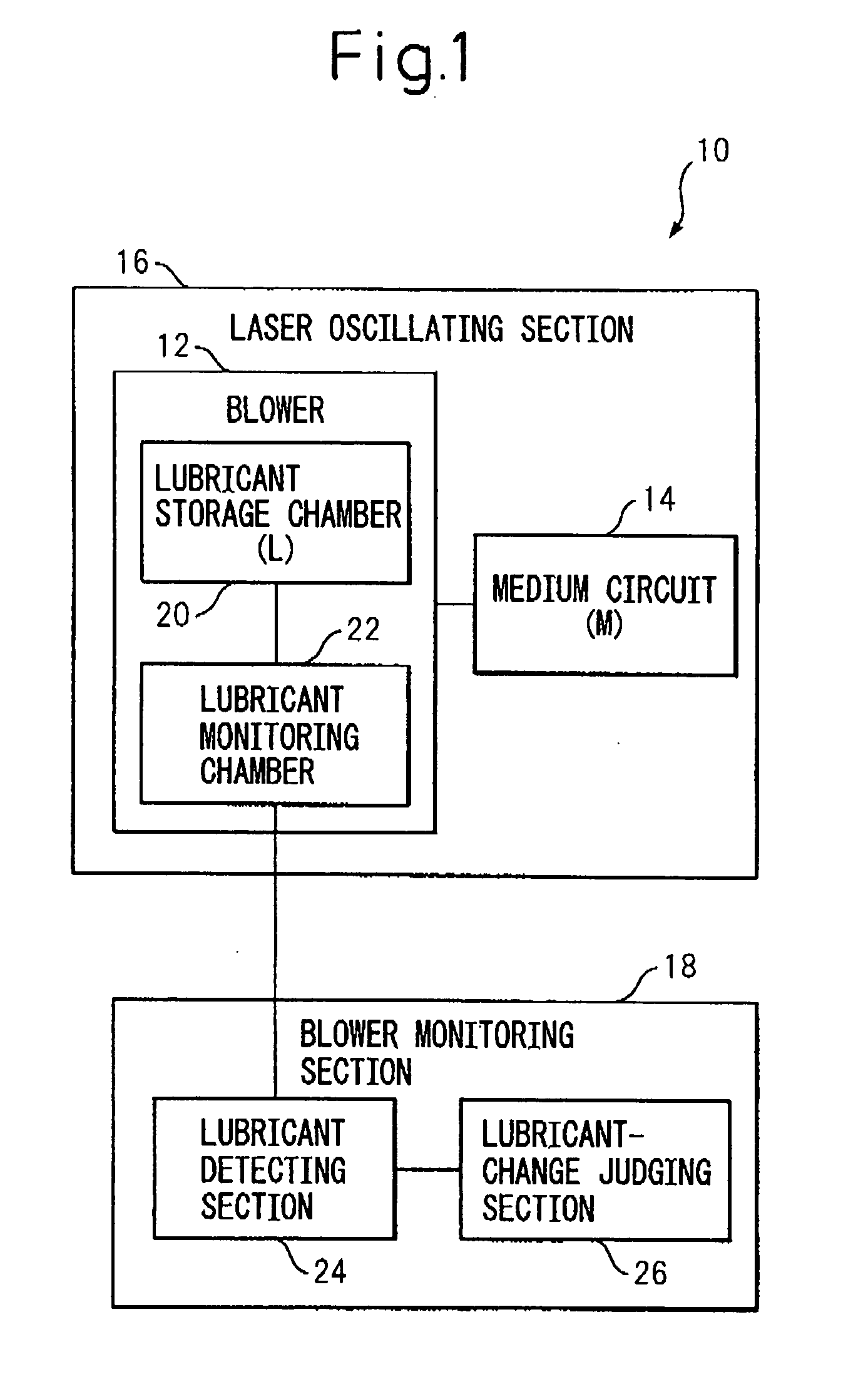
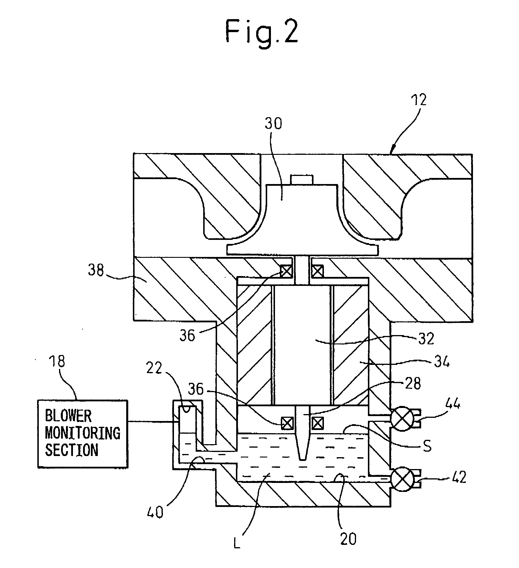
[0029]Referring to the drawings, FIG. 1 is a functional block diagram showing a basic configuration of a gas laser apparatus 10 according to the present invention, and FIG. 2 is an illustration schematically showing an example of a configuration of a blower 12 provided in the gas laser apparatus 10.

[0030]The gas laser apparatus 10 includes a laser oscillating section 16 having a medium circuit 14 for generating a laser beam and including a blower 12 for forcibly circulating a medium gas M in the medium circuit 14; and a blower monitoring section 18 for monitoring a maintenance state (in particular, a lubricant changing state) of the blower 12 of the laser oscillating section 16. The blower 12 includes a lubricant storage chamber 20 for storing a lubricant or lubricating oil L; ...


PUM


Abstract

A gas laser apparatus including a laser oscillating section including a blower forcibly circulating a medium gas in a medium circuit, and a blower monitoring section monitoring a maintenance state of the blower. The blower includes a lubricant storage chamber storing a lubricant, and a lubricant monitoring chamber connected to the lubricant storage chamber to ensure fluidic communication therebetween at a position lower than an oil level of a lubricant having a predetermined appropriate volume and stored in the lubricant storage chamber. The blower monitoring section includes a lubricant detecting section detecting that a lubricant stored in the lubricant storage chamber of the blower flows into the lubricant monitoring chamber and at least a part of the lubricant is present in the lubricant monitoring chamber, as a result of internal-pressure change in the lubricant storage chamber, and a lubricant-change judging section monitoring whether the lubricant detecting section detects a presence of the lubricant in the lubricant monitoring chamber, before the laser oscillating section is activated, and judging that, when the lubricant detecting section does not detect the presence, the lubricant stored in the lubricant storage chamber is in a state immediately after a lubricant change.

Description

BACKGROUND OF THE INVENTION[0001]1. Field of the Invention[0002]The present invention relates to a gas laser apparatus using a gaseous laser medium. The present invention also relates to a method and device for monitoring a maintenance state of a blower adapted to be provided in a gas laser apparatus.[0003]2. Description of the Related Art[0004]A gas laser apparatuses using a gaseous laser medium is widely used in the field of processing, medical care, measurement and so on. A laser oscillating section of the gas laser apparatus generally includes an excitation section for exciting, by electrical discharge, light, heat, chemical reaction and the like, a flowable gas acting as a laser medium (referred to as a medium gas in this application); a light resonance section, having a pair of mirrors, for amplifying light energy of the medium gas excited by the excitation section and generating a laser beam; and a blower for forcibly circulating the medium gas in a medium circuit including t...

Claims


Application Information

Patent Timeline
Patent Type & Authority Applications(United States)
IPC IPC(8): H01S3/036F01M1/18F04D27/00F16N29/00
CPCH01S3/0014H01S3/104H01S3/036
Inventor OHTA, KAZUYAEGAWA, AKIRA
Owner FANUC LTD
Why Eureka
Try Eureka