Aperture variable inspection optical system and color filter evaluaton process

a variable inspection and color filter technology, applied in the field of inspection optical systems, can solve the problem of the size of the pixel of the color filter becoming larger, and achieve the effect of maintaining the shape precision of the aperture and reducing the rattling of the second slide pla

Inactive Publication Date: 2008-03-06
OTSUKA DENSHI CO LTD
View PDF3 Cites 10 Cited by
  • Summary
  • Abstract
  • Description
  • Claims
  • Application Information

AI Technical Summary

Benefits of technology

[0016]This arrangement enables formation of an irradiation spot in any size at the position of the sample. When the irradiation spot is formed so as to coincide with the entire area of one pixel, it is possible to measure optical characteristics of the entire area of one pixel. The shape of the irradiation spot can be automatically changed in accordance with the shape of any given pixel. In addition, it is not necessary to prepare a plurality of aperture units in different sizes for samples with different pixel sizes because the shape of the aperture can be adjusted at each measurement.
[0018]When the proximal end of the second slide plate is biased by means of a spring, rattling of the second slide plate can be reduced, so that precision in shape of the aperture can be maintained.

Problems solved by technology

However, recently, as the display screens of liquid crystal display devices become larger, the size of the pixel of a color filter becomes larger.

Method used


Image

  • Aperture variable inspection optical system and color filter evaluaton process
  • Aperture variable inspection optical system and color filter evaluaton process
  • Aperture variable inspection optical system and color filter evaluaton process

Examples


Embodiment Construction

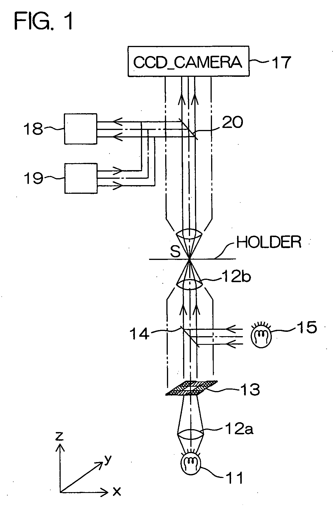
[0039]FIG. 1 is a schematic diagram showing the overall structure of an aperture variable inspection optical system.

[0040]The aperture variable inspection optical system according to the present invention comprises a light projecting optical unit for projecting an irradiation spot on a sample S and a light receiving optical unit for receiving light transmitted through the sample S for measurement thereof.

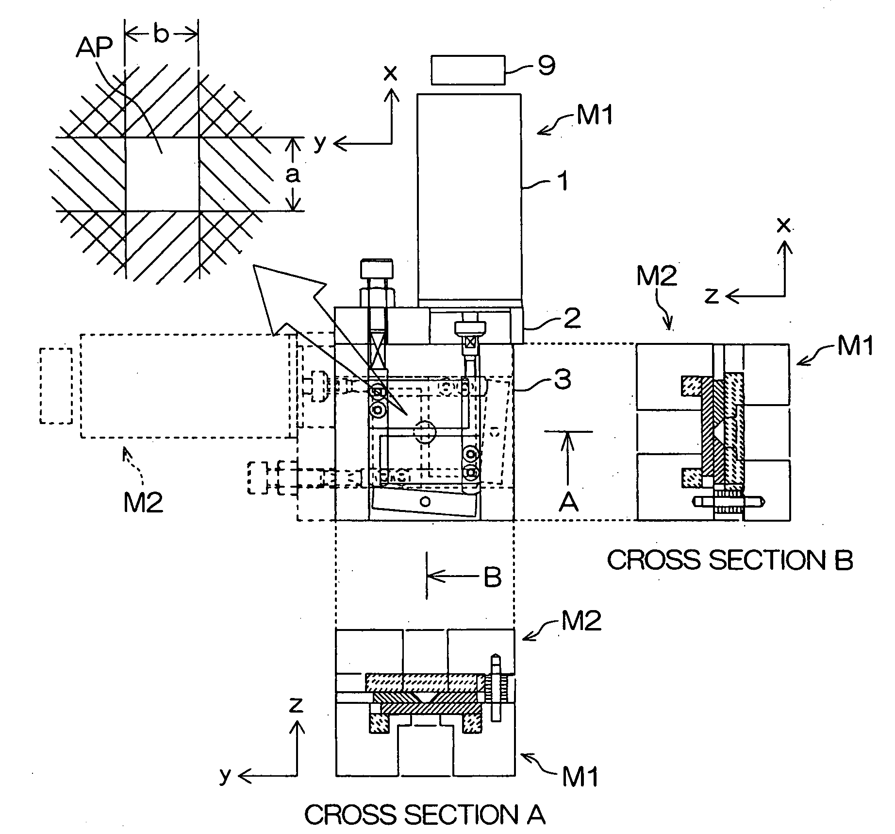
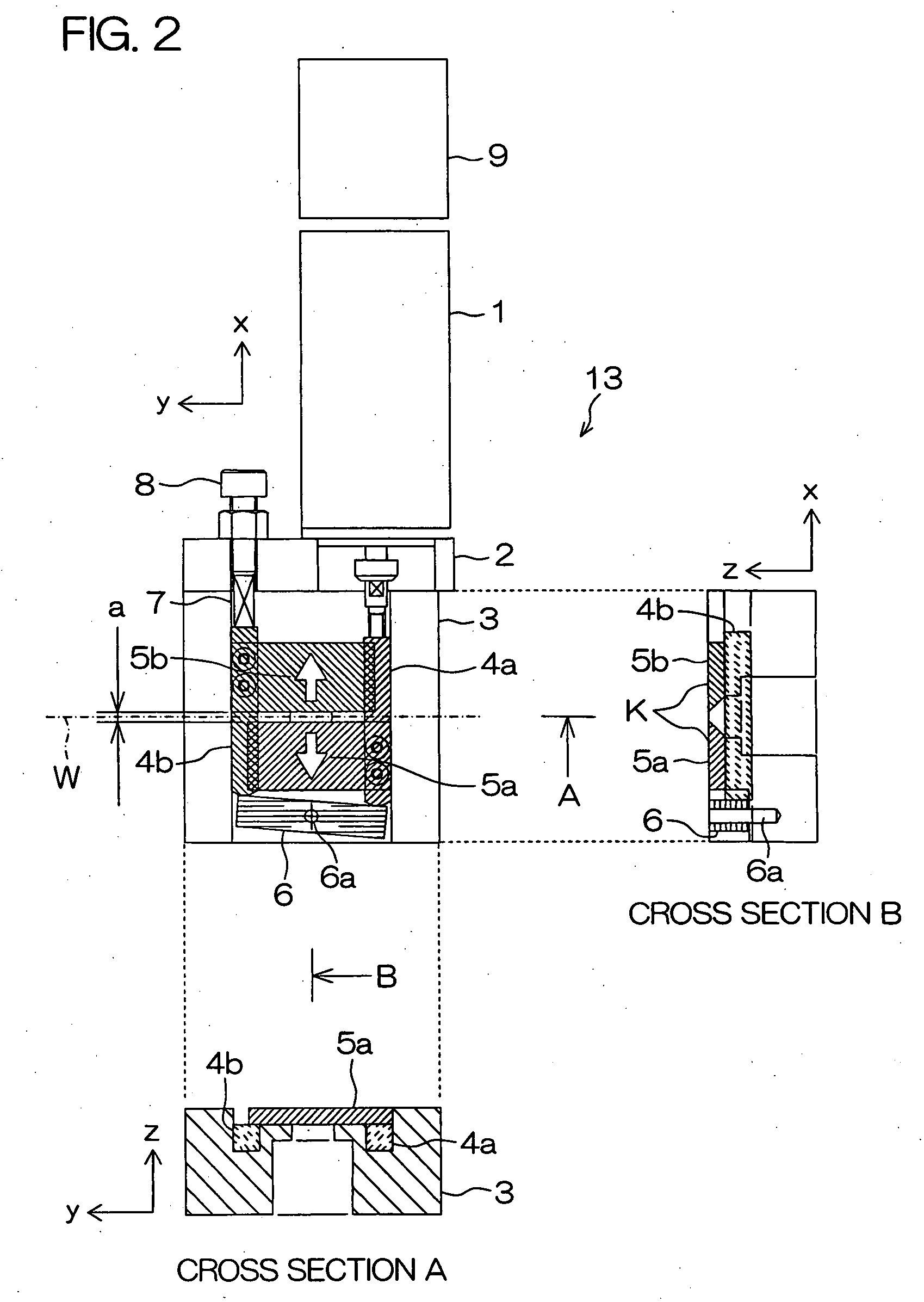
[0041]The light projecting optical unit includes a transmittance measurement light source 11 for projecting light for measurement on the sample S, lens systems 12a, 12b for converging the light from the transmittance measurement light source 11 onto the sample S, a variable aperture unit 13 for forming a quadranglar aperture that is interposed between the transmittance measurement light source 11 and the sample S, a half mirror 14 interposed between the transmittance measurement light source 11 and the sample S, and a transmittance observation light source 15 for projecting light on...


PUM

PropertyMeasurementUnit
angleaaaaaaaaaa
rotation angleaaaaaaaaaa
degree of angleaaaaaaaaaa

Abstract

Disclosed is an aperture variable inspection optical system including a variable aperture unit 13 having a polygonal light transparent section and light collecting systems 12a, 12b for forming an irradiation spot U of light passing through the variable aperture unit 13 at the position of a sample S. The variable aperture unit 13 is capable of changing the shape / size of the polygon. The size of the irradiation spot U can be changed without rearranging the aperture unit.

Description

BACKGROUND OF THE INVENTION[0001]1. Field of the Invention[0002]The present invention relates to an inspection optical system that is suitably used for inspection of optical characteristics of color filters incorporated in liquid crystal display devices and the like.[0003]2. Description of Related Art[0004]A color filter for a liquid crystal display device generally consists of three color filters including R, G, and B. In this specification, the range covered by one R filter, the range covered by one G filter, and the range covered by one B filter are each defined as one pixel.[0005]Evaluations of optical characteristics of this color filter are carried out such that a light spot from a measurement light source is projected onto the center of one pixel of R, transmittance spectrum, chromaticity, white balance, etc. of the central area are measured. The same measurements are made on the pixels of G and B. The color filter to be measured is referred to as the “sample”.[0006]FIG. 14 s...

Claims


Application Information

Patent Timeline
Patent Type & Authority Applications(United States)
IPC IPC(8): G01N21/01
CPCG01N21/25G02B21/086G02B5/201G01N21/00G01N21/59G02B27/00
Inventor NAKAMURA, KENJISHIRAIWA, HISASHI
Owner OTSUKA DENSHI CO LTD
Why Eureka
Try Eureka