Substrate holding apparatus, and inspection or processing apparatus

Inactive Publication Date: 2008-03-06
HITACHI HIGH-TECH CORP
View PDF2 Cites 3 Cited by
  • Summary
  • Abstract
  • Description
  • Claims
  • Application Information

AI Technical Summary

Benefits of technology

[0007] In a conventional substrate holding apparatus, in order to make the rotation of a substrate smooth, the substrate is positioned on the substrate holding apparatus so that a normal line of the substrate passing through the center of gravity of the substrate coincides with the rotation axis of the substrate holding apparatus. Then, there is a tendency for a circuit pattern, etc. to be miniaturized, and in order to maintain the repeatability of processing and inspection, it has been considered that it is necessary to improve the positioning accuracy. For example, in the case of a miniaturized circuit pattern, in order to determine on which pattern a foreign material is positioned, it is necessary to improve the accuracy of the coordinate of the foreign material.
[0009] In addition, the substrate may be warped in the manufacturing process, due to a heating process, or formation of a metal film. In the conventional substrate holding apparatus, the substrate is held while being warped, since the substrate holding apparatus is not in contact with the front surface and the backside of the substrate. Since this warping also causes variation of the distance between the substrate and the optical device, the flatness of the substrate has been improved by blowing a gas with a high cleanliness factor to the backside of the substrate in order to correct the warping. In the future, if the heat processing becomes used frequently or a large number of metal films become formed in a manufacturing process, it is considered that the warping becomes larger, and the blowing for correcting it will become also strong. In order to prevent the substrate from floating up by the blowing, it is considered that stronger force is necessary to press the substrate against the inclined surface which supports the substrate.
[0010] In view of the above, the objects of the present invention is to provide a substrate holding apparatus enabling highly accurate positioning and strong pressing of the substrate to solve the above mentioned problems, and to provide an inspection or processing apparatus using this substrate holding apparatus.
[0012] According to the present invention, it is possible to provide a substrate holding apparatus enabling high accuracy positioning and strong pressing of a substrate, and further, provide an inspection or processing apparatus using this substrate holding apparatus.

Problems solved by technology

The width of the variation becomes larger than the depth of focus of the optical device, which depth has been reduced corresponding to miniaturization of a pattern, and, it has been considered that this degrades the sensitivity of the optical device.
In addition, the substrate may be warped in the manufacturing process, due to a heating process, or formation of a metal film.

Method used


Image

  • Substrate holding apparatus, and inspection or processing apparatus
  • Substrate holding apparatus, and inspection or processing apparatus
  • Substrate holding apparatus, and inspection or processing apparatus

Examples


Embodiment Construction

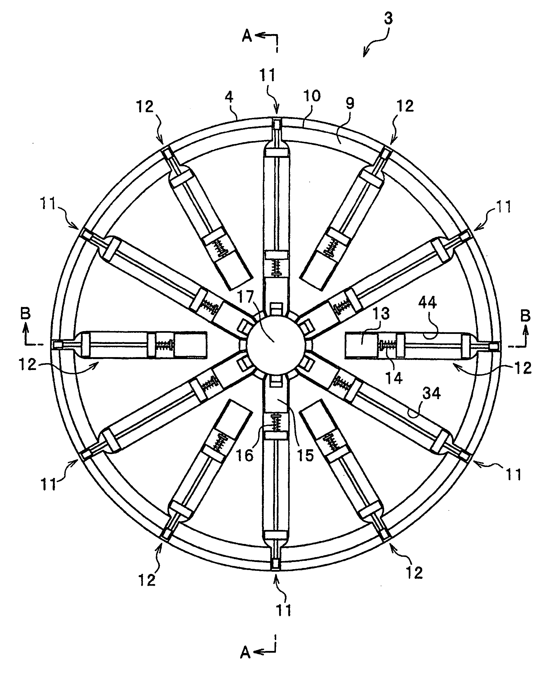
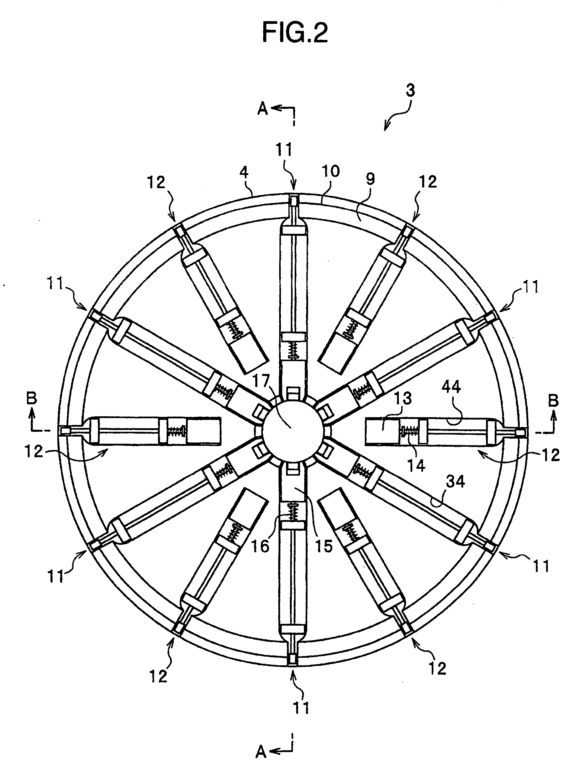
[0025] Next, an embodiment of the present invention will be described in detail with reference to the drawings appropriately. In addition, a common part is denoted by the same reference numeral in the respective drawings, to eliminate duplicate explanation.

[0026] An inspection or processing apparatus according to an embodiment of the present invention inspects or processes a substrate such as a semiconductor wafer, a glass substrate and a disk substrate, in a manufacturing process of a product such as a semiconductor device, a thin display and a magnetic disk. As an inspection apparatus, it is used for a surface inspection apparatus which inspects the substrate for defects or foreign materials thereon while rotating the substrate, a particle counter or the like. As a processing apparatus, it is used for a liquid chemical processing apparatus for subjecting the substrate to liquid chemical processing, cleaning and drying while rotating the substrate, a spin coater for coating, devel...


PUM


Abstract

In order to enable high accuracy positioning and strong pressing of a substrate, the present invention provides a substrate holding apparatus including: a rotating bed having an inclined surface supporting a lower side of an outer circumferential side surface of the substrate, which bed rotates on a normal line of the substrate as the rotation axis together with the substrate; a position restriction unit rotating together with the rotating bed and restricting the substrate in a predetermined position on the rotating bed by pressing a plurality of points on the circumference on an upper side of the outer circumferential side surface of the substrate prior to the rotation; and a pressing unit rotating together with the rotating bed and pressing the substrate against the inclined surface by pressing a plurality of points on the upper side of the outer circumferential side surface of the substrate during the rotation.

Description

BACKGROUND OF THE INVENTION [0001] 1. Field of the Invention [0002] The present invention relates to a substrate holding apparatus which rotates together with a substrate while supporting an outer circumferential side surface of the substrate, and an inspection or processing apparatus of a substrate using this substrate holding apparatus. [0003] 2. Description of Related Art [0004] In a manufacturing process of a product such as a semiconductor device, a thin display and a magnetic disk, a substrate such as a semiconductor wafer, a glass substrate and a disk substrate is processed, and the processed substrate is inspected. In many cases, the processing and the inspection of the substrate are performed while rotating the substrate. For example, in surface inspection for determining whether a defect such as a flaw or a foreign material is present on a surface of the semiconductor wafer or not, the inspection light scans the surface of the semiconductor wafer in a spiral manner by movi...

Claims


Application Information

Patent Timeline
IPC IPC(8): G01N21/86H01L21/68
CPCG01N21/9501H01L21/68728G01N21/9506
Inventor ZAMA, KAZUHIROASAMI, KOICHIMIYAZAKI, YUSUKE
Owner HITACHI HIGH-TECH CORP
Why Eureka
Try Eureka