Dry fiber wrapped pipe

Inactive Publication Date: 2008-03-06
CONOCOPHILLIPS CO
View PDF25 Cites 23 Cited by
  • Summary
  • Abstract
  • Description
  • Claims
  • Application Information

AI Technical Summary

Benefits of technology

[0009]The present invention relates to a reinforced pipe section comprising a metal pipe, a layer of dry fibers disposed around the metal pipe, and an external liner covering the layer of dry fibers. In an embodiment, the layer of dry fibers increases the hoop strength of the metal pipe. In other embodiments, the metal pipe is comprised of conventional steel pipe having a yield strength of approximately 70,000 psi (X70) or less, or high strength steel pipe having a minimum yield strength of greater than 70,000 psi. The metal pipe may comprise a corrosion resistant alloy. In an embodiment, the metal pipe arrests a crack that may develop during service. The metal pipe may comprise bare pipe or coated pipe, wherein the metal pipe may be pre-coated with an organic coating or with an anodic metallic coating. In other embodiments, the metal pipe is corrosion protected by an aluminum anode strip wound onto the metal pipe, or by a pH spiking salt applied to the layer of dry fibers. In another embodiment, the metal pipe comprises a degraded pipe.
[0013]In yet another aspect, the present invention relates to a method of reinforcing a degraded metal pipe comprising wrapping the degraded metal pipe with a layer of dry fibers to increase the hoop strength of the degraded metal pipe, and covering the layer of dry fibers with an external liner.

Problems solved by technology

Often, however, the high cost of building the infrastructure necessary to deliver natural gas from such remote locations negates the financial incentives to develop these sources.
High strength steel has a relatively low crack resistance, so if a pipe were to become damaged and a crack were to form, that crack may propagate along the pipeline for many miles.
In addition, high strength steel manufacturing capacity is low, welding of high strength steel is complicated, and high strength steels have a lower plastic strain capacity than conventional steels, which may limit their use in applications requiring a high plastic strain capacity, such as pipelines installed in permafrost and seismic areas, for example.

Method used


Image

  • Dry fiber wrapped pipe
  • Dry fiber wrapped pipe
  • Dry fiber wrapped pipe

Examples


examples

[0044]Various tests were conducted to demonstrate the feasibility of using conventional strength steel pipe wrapped with dry fibers as an alternative to high strength steel or composite wrapped steel in high-pressure applications.

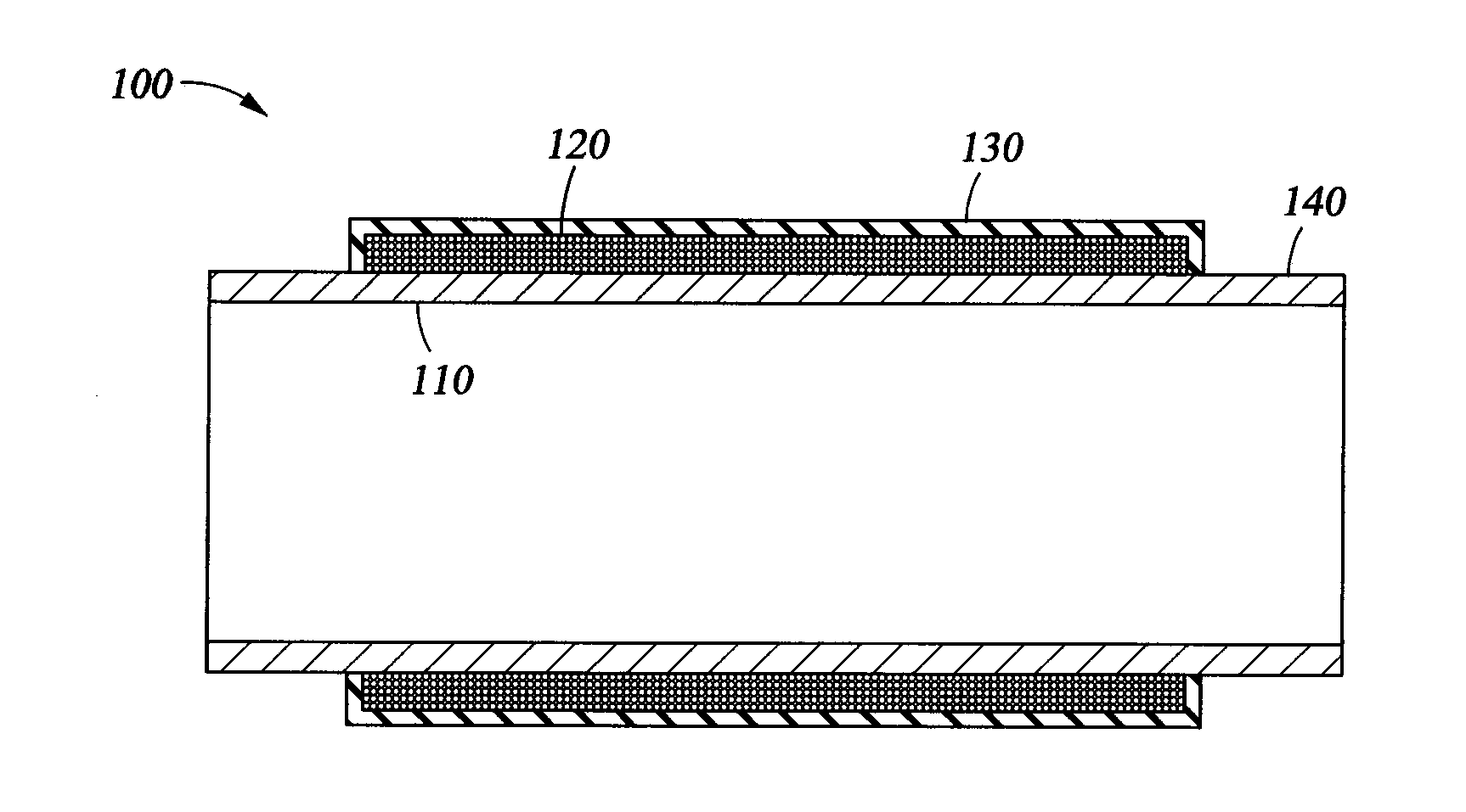
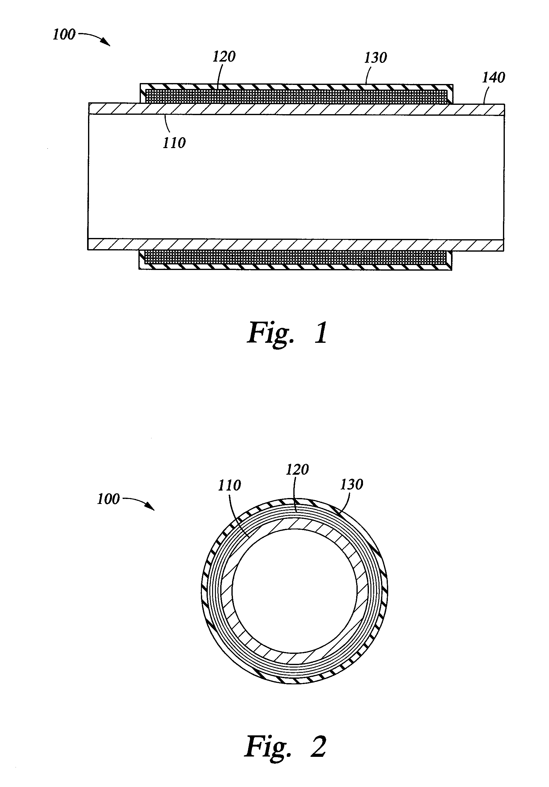
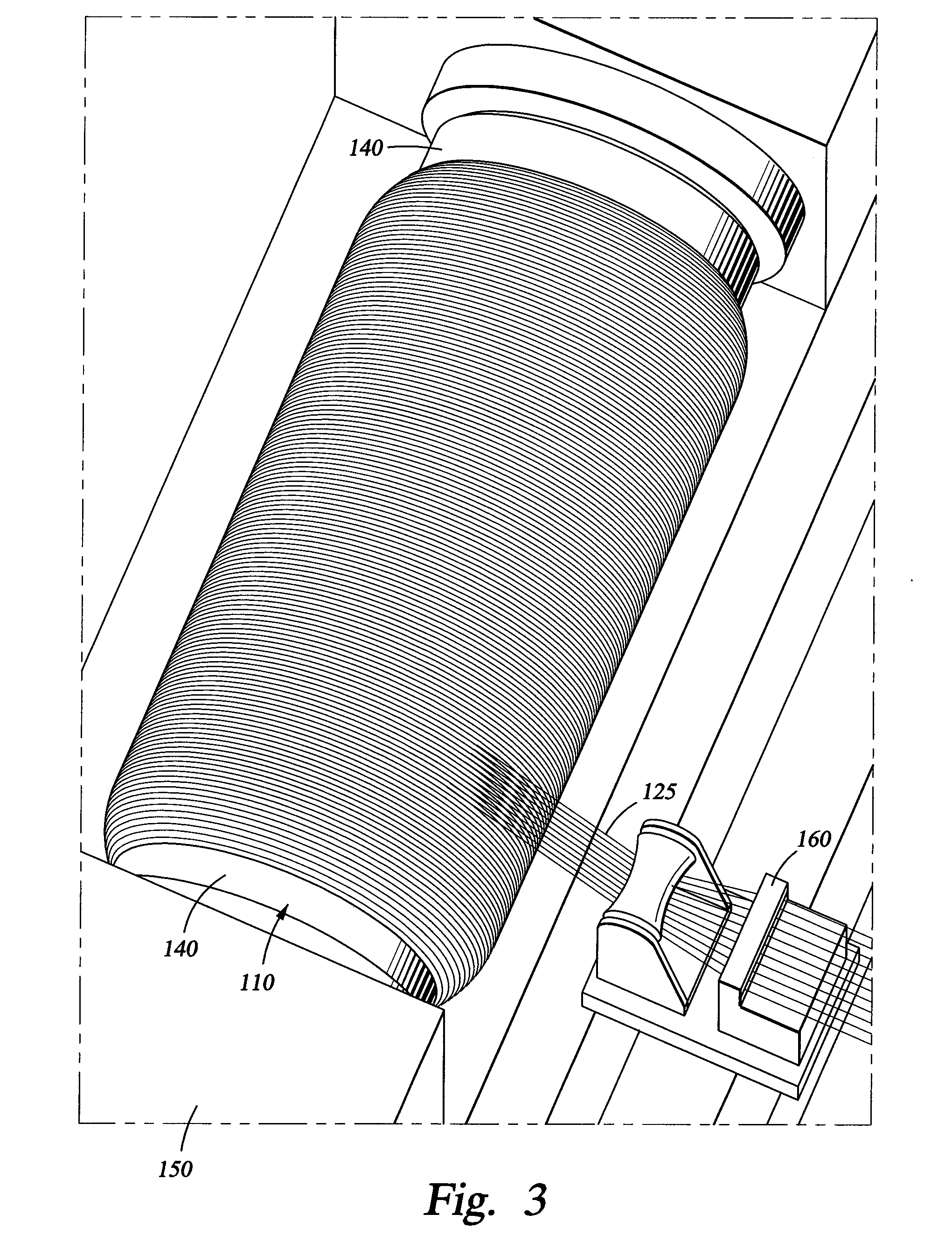
[0045]One section of 12-inch nominal diameter X70 pipe having a wall thickness of 0.25 inches was hoop-wound with 0.35 inches of dry fiberglass and then sprayed with a 0.1 inch layer of polyurea, which dried to form an elastomeric liner. An internal pressure of 4,500 psi was applied to the pipe section for approximately 5 minutes and then released. The internal pressure was then increased to failure, which occurred at approximately 7,800 psi at a girth weld.

[0046]This test indicates that the layer of dry fiberglass significantly increased the pressure rating of the X70 pipe and also changed the failure mode from hoop (burst) to axial failure. Without the fiberglass wrap, the 12-inch X70 pipe with a wall thickness of 0.25 inches should have failed by burst p...


PUM

PropertyMeasurementUnit
Yield strengthaaaaaaaaaa
Thicknessaaaaaaaaaa
Diameteraaaaaaaaaa

Abstract

A reinforced pipe section comprises a metal pipe, a layer of dry fibers disposed around the metal pipe, and an external liner covering the layer of dry fibers. A method of manufacturing a reinforced pipe section comprises wrapping a layer of dry fibers over a metal pipe, and covering the layer of dry fibers with an external liner, thereby forming a first dry fiber wrapped metal pipe. A method of reinforcing a degraded metal pipe comprises wrapping the degraded metal pipe with a layer of dry fibers to increase the hoop strength of the degraded metal pipe, and covering the layer of dry fibers with an external liner.

Description

CROSS-REFERENCE TO RELATED APPLICATIONS[0001]None.STATEMENT REGARDING FEDERALLY SPONSORED RESEARCH OR DEVELOPMENT[0002]Not applicable.REFERENCE TO A MICROFICHE APPENDIX[0003]Not applicable.FIELD OF THE INVENTION [0004]The present disclosure relates generally to reinforced metal pipe sections comprising dry fiber wrapped metal pipes for use in high-pressure fluid transport applications, and methods for manufacturing reinforced pipe sections of this type.BACKGROUND [0005]As the worldwide demand for natural gas grows, the need to develop remotely located sources of natural gas becomes increasingly more important. Often, however, the high cost of building the infrastructure necessary to deliver natural gas from such remote locations negates the financial incentives to develop these sources. Thus, there is a need to reduce the costs associated with constructing facilities such as pipelines to deliver natural gas to market.[0006]In recent years, several major oil and gas companies have in...

Claims


Application Information

Patent Timeline
IPC IPC(8): F16L9/00
CPCB29C70/086B29C70/86B29K2021/00B29L2023/22Y10T29/49982F16L9/147F16L55/1686Y10T29/49746F16L9/04
Inventor SALAMA, MAMDOUH M.
Owner CONOCOPHILLIPS CO
Why Eureka
Try Eureka