
Combination of a cylinder liner and a piston ring

a technology of cylinder liner and piston ring, which is applied in the direction of piston rings, machines/engines, cylinders, etc., can solve the problems of insufficient performance, inability to obtain sufficient performance, so as to improve the initial fitting and the scuffing resistance of both cylinder lines. , the effect of low friction

Inactive Publication Date: 2008-03-06
NIPPON PISTONRING CO LTD
View PDF5 Cites 43 Cited by
  • Summary
  • Abstract
  • Description
  • Claims
  • Application Information

AI Technical Summary

Benefits of technology

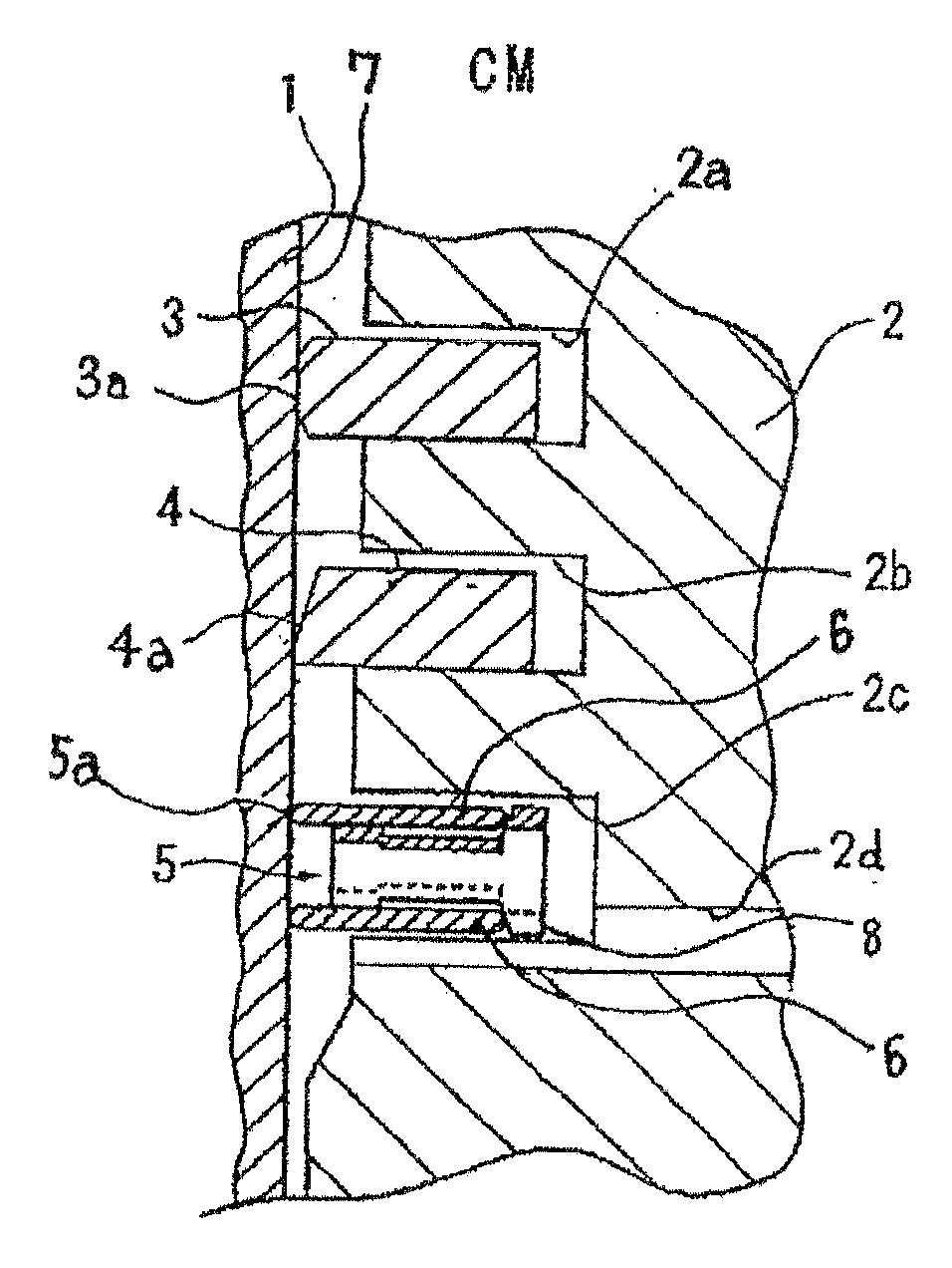
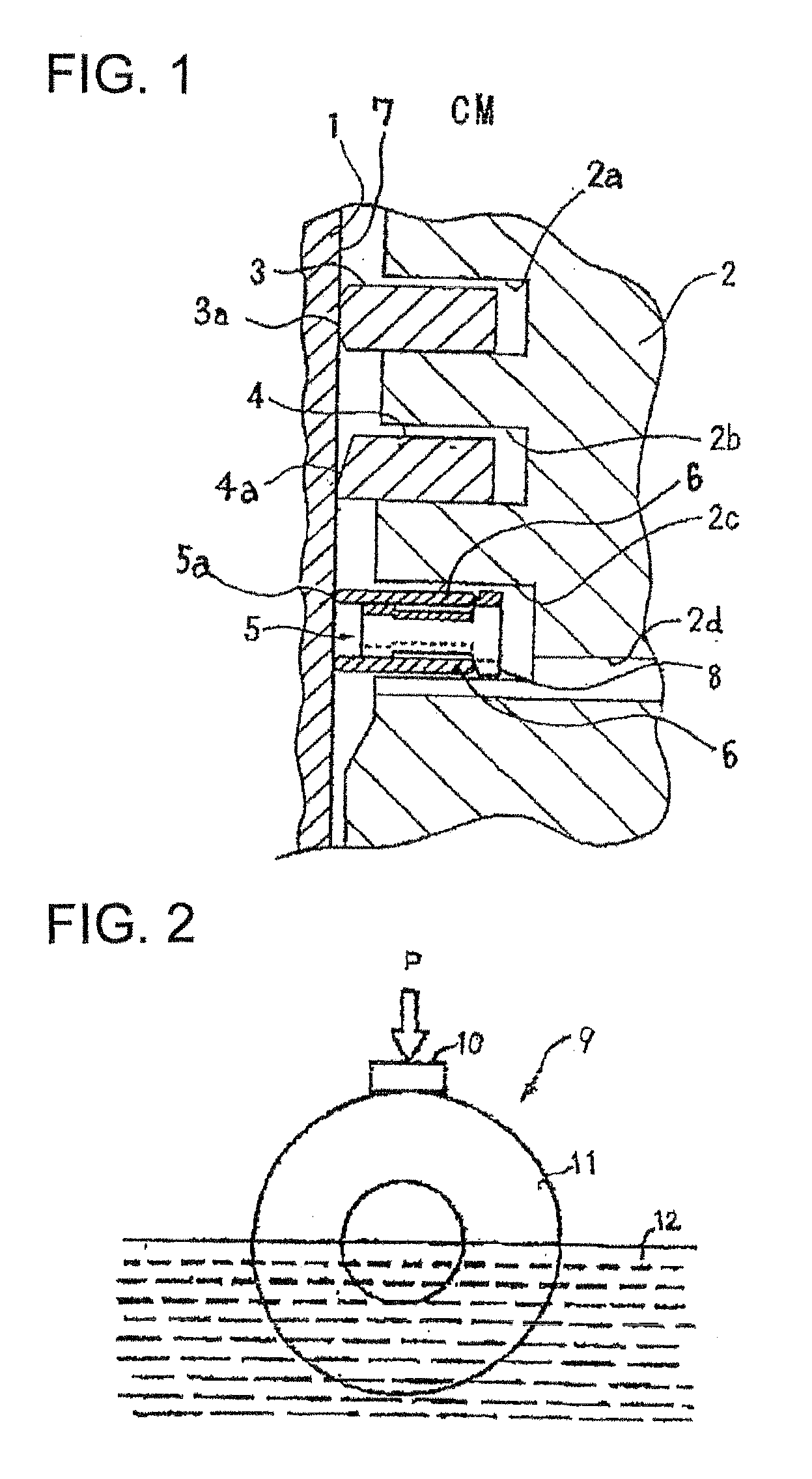
[0018] The present invention was made under such circumstances and it can meet the requirement for the reduction in weight of the current engine. A main problem to be solved by the present invention is to provide these optimal combinations which make low friction between a cylinder liner and a piston ring and the reduction of each other's amount of wear possible, and make it possible to try to improve scuffing resistance.
[0024] According to a combination of a cylinder and a piston ring of the present invention, a composition of a piston ring is determined depending on a contact pressure of an inner circumference surface of the cylinder liner and a sliding piston ring, and furthermore, as both the cylinder liner and the piston ring are limited about the surface roughness using various parameters, it is possible to realize low friction, to reduce the amount of wear and improve the initial fitting and the scuffing resistance of both the cylinder liner and the piston ring.
[0025] Furthermore, in the present invention, the more effect can be produced by forming DLC coating on a surface of a piston ring.

Problems solved by technology

However, sufficient performance cannot be obtained from the combination of the cylinder liner and the piston ring disclosed in Patent Literature 5, and thus there is still room for further improvement.
However, the combination of the cylinder liner and the piston ring disclosed in Patent Literature 5 does not consider this point and it is far from obtaining the sufficient performance.
In addition, as for the cylinder liner disclosed in Patent Literature 4, a sufficient performance is not obtained.
For example, as for such cylinder liner, there was a problem that the frictional force with a piston ring increases when a difference in level between silicon primary crystal or intermetallic compound such as Al2Cu or Mg2Si and Al alloy as a base material, and a corner edge of these compounds which extends to the sliding surface base side, which are caused by chemical polishing (etching), slides with the piston ring.
In addition, when the tension of the piston ring is relatively large as in an oil ring (about 10 times as much as a pressure ring), the wear resistance of the ring and the aggressiveness to the cylinder liner sometimes became a problem.

Method used


Image

  • Combination of a cylinder liner and a piston ring
  • Combination of a cylinder liner and a piston ring

Examples


example

[0109] A combination of a cylinder liner and piston rings according to the present invention will be concretely described by using examples.

examples 1 to 5

[0110] First, as specimens of cylinder liners which each constitutes the combination according to the present invention, test pieces composed of Si: 25% by weight, Mg: 1.2% by weight, Cu: 3.9% by weight, Fe: 0.12% by weight, Ni: 0.008% by weight, Mn: 0.007% by weight, Zn: 0.008% by weight, and the rest: unavoidable impurities and A1 were prepared. Then, surface roughness (Rz, Rpk, Rk, Rvk) of each test piece of the cylinder liner was varied as shown in the following Table 1 so that the individual test pieces became a specimen of the cylinder liner of individual Examples 1 to 15 according to the present invention.

[0111] On the other hand, as specimens of piston rings which each constitutes the combination according the present invention, test pieces composed of C, 0.33% by weight, Si: 0.05% by weight, Mn: 0.05% by weight, Ni: 0.20% by weight, Cr: 13.0% by weight, P: 0.02% by weight, S: 0.01% by weight, and the rest: unavoidable impurities and Fe were prepared. Then, surface roughnes...

examples 1 to 3

Conventional Examples 1 to 3

[0120] A few combinations of cylinder liners and a piston rings were prepared as Conventional Examples.

[0121] Concretely, as specimens of a cylinder liners which each constitutes the combination of Conventional Example, test pieces of the same composition with those of above Examples were prepared. Then, surface roughness (Rz, Rpk, Rk, Rvk) of each test piece of the cylinder liner was varied as shown in the following Table 1 so that the individual test pieces became a specimen of the cylinder liner of individual Conventional Examples 1 to 3.

[0122] On the other hand, as specimens of piston rings which each constitutes the combination of Conventional Example, test pieces of the same composition with those of above Examples were prepared. Then, surface roughness (Rz, Rpk) of each test piece of the piston ring and the area ratio of carbide (diameter: 0.1 to 1.5 μm) were varied as shown in the following Table 1 so that the individual test pieces became a spe...


PUM


Abstract

The disclosed is a combination of a cylinder liner and a piston ring which contacts to a inner circumference surface of the cylinder liner at the pressure of 0.03 to 0.2 MPa, wherein the composition of the cylinder liner includes, silicon: 23.0 to 28.0% by weight, magnesium: 0.80 to 2.0% by weight, copper: 3.0 to 4.5% by weight, iron: 0.25% by weight or less, nickel: 0.01% by weight or less, and the rest: unavoidable impurities and aluminum, and wherein surface roughness profile of the inner circumference surface has Rz 0.5 to 1.0 μm, Rk=0.2 to 0.4 μm, Rpk=0.05 to 0.1 μm, Rvk=0.08 to 0.2 μm, meanwhile, wherein the composition of a piston ring includes carbon: 0.6 to 0.7% by weight, chrome: 13 to 14% by weight, molybdenum: 0.2 to 0.4% by weight, silicon: 0.25 to 0.50% by weight, manganese: 0.2 to 0.5% by weight, and the rest: unavoidable impurities and iron, and wherein carbides with the diameter of 5.0 μm and less are contained at the area rate of 4 to 10%, and the surface roughness of an outer circumference sliding surface is Rz=0.8 μm or less, and RPk=0.15 μm or less.

Description

BACKGROUND OF THE INVENTION [0001] 1. Field of the Invention [0002] The present invention relates to a combination of a cylinder liner and a piston ring, more particularly, to a combination of a cylinder liner used for an internal-combustion engine for automobiles, lawn mowers, generators, etc. and a piston ring which slides on an inner circumference surface of such cylinder liner. [0003] 2. Related Art [0004] In recent years, in order to improve fuel economy and kinematic performance, a reduction in weight of a whole automobile has been promoted, and, with such reduction in weight or a whole automobile, it is natural that the engine has also become a target of the reduction in weight. [0005] In order to try to reduce the weight of an engine, it has been developed to use light alloy typified by magnesium alloy or aluminum alloy for a cylinder liner and a cylinder block which is cast so as to envelope the cylinder liner. As an illustrative embodiment of these cylinder liners and cyli...

Claims


Application Information

Patent Timeline
IPC IPC(8): F02F1/00
CPCF16J9/00
Inventor HIRAISHI, IWAOOGAWA, KATSUAKIISHIKAWA, HIROMIHIRASE, TSUGANESAMESHIMA, KAZUHIRO
Owner NIPPON PISTONRING CO LTD
Learn More