
Method of generating electrolyzed water and electrolyzed water generation apparatus therefor

a technology electrolyte water, which is applied in the direction of water/sewage treatment by neutralisation, water treatment parameter control, specific water treatment objectives, etc., can solve the problem of resource saving, difficult to perform in ordinary homes or the like, and stronger alkalinity of electrolyte aqueous solution

Inactive Publication Date: 2008-02-28
HONDA MOTOR CO LTD
View PDF8 Cites 35 Cited by
  • Summary
  • Abstract
  • Description
  • Claims
  • Application Information

AI Technical Summary

Benefits of technology

[0010] In view of the above-described problems, an object of the present invention is to provide an electrolyzed water generation method easy to carry out in ordinary homes or the like and an electrolyzed water generation apparatus used in accordance with the method.

Problems solved by technology

However, there are only a small number of instances of use requiring both the acid electrolyzed water and the alkaline electrolyzed water.
This is problematic in terms of resource saving.
However, the electrolyte aqueous solution exhibits stronger alkalinity if the circulation time is increased.
Therefore the neutralizing operation using acetic acid or the like requires sufficiently elaborate management and is difficult to perform in ordinary homes or the like.
Also, the time taken to perform the neutralizing operation is disadvantageously long.

Method used


Image

  • Method of generating electrolyzed water and electrolyzed water generation apparatus therefor
  • Method of generating electrolyzed water and electrolyzed water generation apparatus therefor

Examples


example

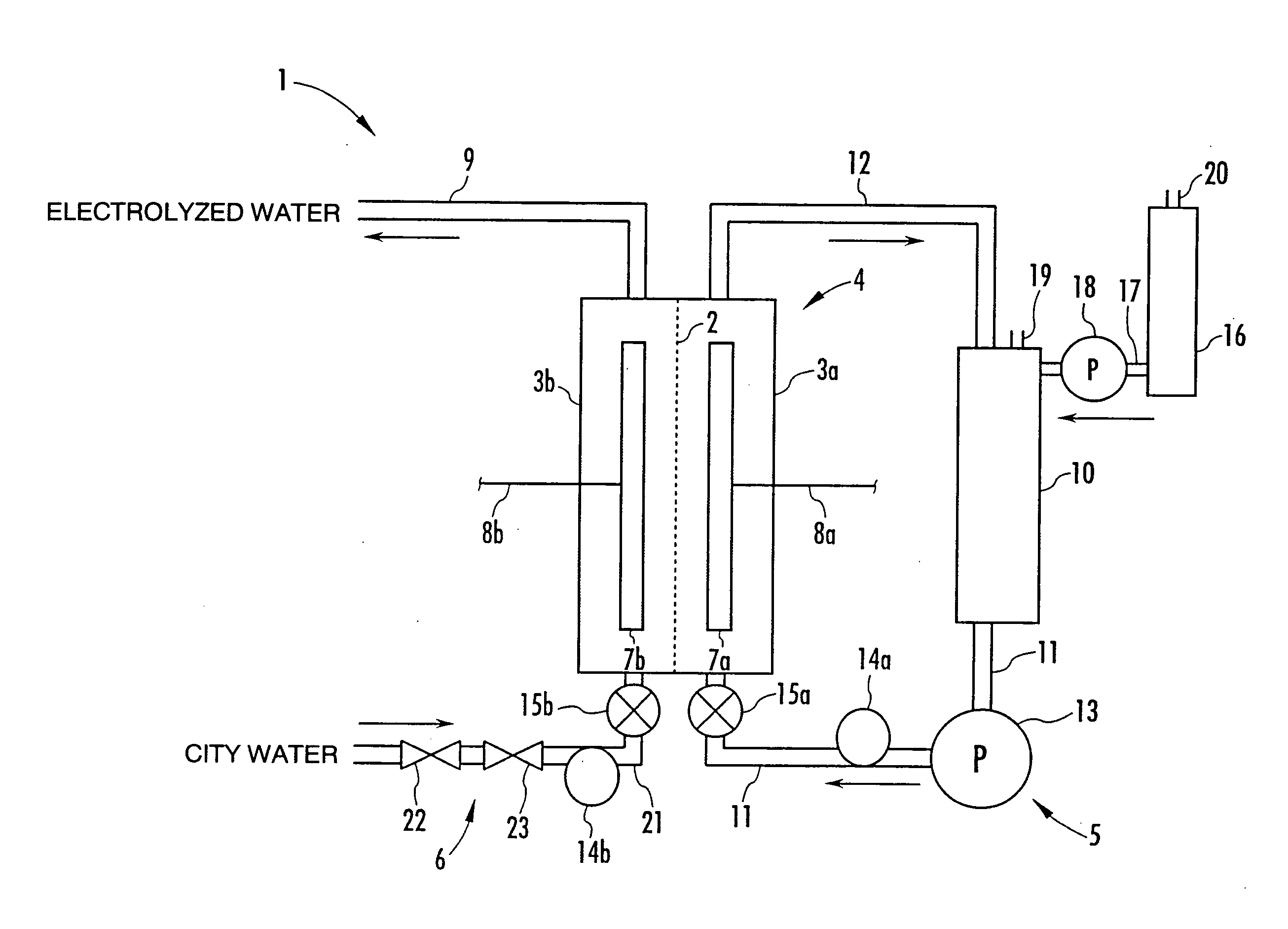
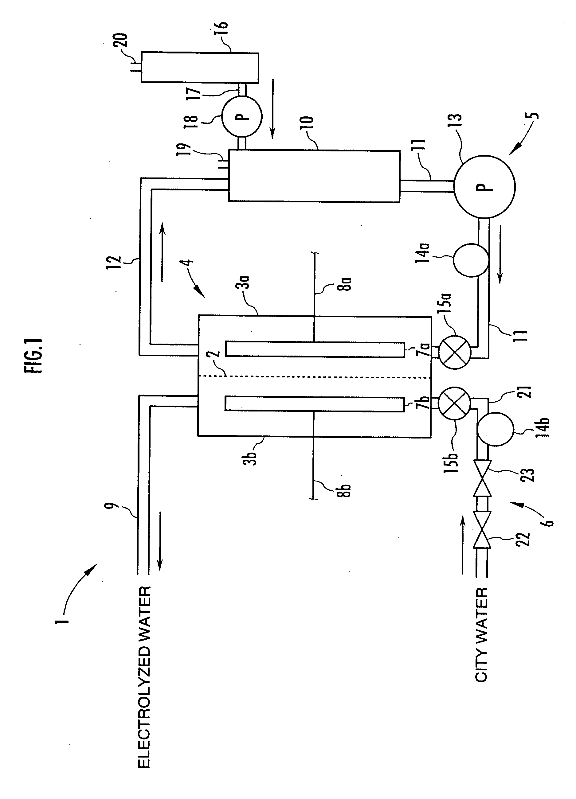
[0051] In the electrolyzed water generation apparatus 1 shown in FIG. 1, in an example of the present invention described below, an anion-exchange membrane was used as the membrane 2; the electrode 7a disposed in the electrolysis chamber 3a was a cathode; and the electrode 7b disposed in the electrolysis chamber 3b was an anode. A 0.1 mol / l sodium chloride aqueous solution was circulated at a flow rate of 1 l / min through the electrolysis chamber 3a by the electrolyte aqueous solution circulation system 5, while city water was supplied as raw water at a flow rate of 1 l / min to the electrolysis chamber 3b through the raw water supply passage 21. A predetermined voltage was applied between the electrodes 7a and 7b from the power supply unit (not shown) to perform constant-current electrolysis at 10A.

[0052] The pH of the sodium chloride aqueous solution circulated through the electrolysis chamber 3a by the electrolyte aqueous solution circulation system 5 was measured with the pH senso...


PUM

PropertyMeasurementUnit
pHaaaaaaaaaa
flow rateaaaaaaaaaa
voltageaaaaaaaaaa

Abstract

A method and apparatus for generating electrolyzed water easy to carry out or handle even in ordinary homes. An electrolyte aqueous solution is circuited through a first electrolysis chamber 3a of two electrolysis chambers placed on opposite sides of an ion-permeable membrane 2, and raw water is supplied only to the second electrolysis chamber 3b. A voltage is applied between electrodes 7a and 7b to cause electrolysis. Electrolyzed water generated in the second electrolysis chamber 3b is drawn out. The concentration of the electrolyte aqueous solution circulated through the first electrolysis chamber 3a is maintained within a predetermined range. The membrane 2 is an anion-exchange membrane. The electrolyte aqueous solution is circulated through the first cathode-side electrolysis chamber 3a; raw water is supplied only to the second anode-side electrolysis chamber 3b; and acid electrolyzed water generated in the anode-side electrolysis chamber 3a is drawn out. The electrolyte aqueous solution is NaCl or KCl aqueous solution. The concentration is maintained within the predetermined range by adding hydrochloric acid according to the pH of the NaCl or KCl solution or the amount of reaction of this solution computed from the amount of energization during the electrolysis.

Description

BACKGROUND OF THE INVENTION [0001] 1. Field of the Invention [0002] The present invention relates to a method of generating acid or alkaline electrolyzed water and an electrolyzed water generation apparatus therefor. [0003] 2. Description of the Related Art [0004] A method of generating electrolyzed water is known in which electrodes are respectively disposed in a pair of opposed electrolysis chambers having an ion-permeable membrane therebetween such as an anion-permeable membrane; raw water is supplied to each electrolysis chamber; and a voltage is applied between the electrodes to electrolyze the raw water supplied to each electrolysis chamber. According to this conventional method, a chloride such as sodium chloride is added as an electrolyte to the raw water to obtain acid electrolyzed water containing hypochlorous acid from the electrolysis chamber on the anode side and to obtain alkaline electrolyzed water from the electrolysis chamber on the cathode side. [0005] The above-de...

Claims


Application Information

Patent Timeline
Patent Type & Authority Applications(United States)
IPC IPC(8): C02F1/461C25B9/00
CPCC02F1/4618C02F1/66C02F2201/46115C02F2201/46145C02F2303/08C02F2201/46185C02F2209/06C02F2209/29C02F2201/4618C02F1/46104C02F1/467C25B1/26C25B1/265C02F2201/4612C02F2209/05
Inventor MIYASHITA, KOHICHI
Owner HONDA MOTOR CO LTD
Learn More