Methods for ESD Protection

a non-volatile memory and protection method technology, applied in the direction of coupling device details, coupling device connection, printed circuit, etc., can solve the problems of easy loss or damage, easy damage, and easy damage to connectors, so as to prevent damage or failure of memory devices

Active Publication Date: 2008-02-21
SANDISK TECH LLC
View PDF24 Cites 18 Cited by
  • Summary
  • Abstract
  • Description
  • Claims
  • Application Information

AI Technical Summary

Benefits of technology

[0006]A unit with a retractable connector generally has a feature on the outside of its housing that allows a user to manually slide the connector between a retracted position and an extended position. In the retracted position, the connector is contained within the housing and is protected by the housing. In the extended position, the connector extends through an opening in the housing so that it may be plugged into a receptacle. Such an opening is generally made somewhat larger than the connector so that there is some clearance around the connector to allow it to freely extend and retract without significant friction or binding.
[0007]Under normal circumstances, some electrostatic charge can develop on the conductive housing which may lead to Electrostatic Discharge (ESD) issues. ESD is a discharge of transient charge that may develop on a conductive housing or on a body that is in electrical contact with the housing, causing the housing to be at higher electrical potential with respect to ground requiring a ground path to discharge. Hence many electrical / electronic systems are furnished with ESD protection circuits. These circuits prevent an unwanted transient charge that may develop on a conductive housing from jumping onto sensitive components within the memory system and hence prevent the damage or failure of memory devices. One way to design for ESD protection is to provide a ground path to chassis (PC) ground via a metal shell of a connector.
[0008]A conductive spring provided between the connector and the housing provides an electrically conductive pathway between the housing and the metal shell of the connector. Thus, the housing and the metal shell are kept at the same potential. When the connector is connected to a receptacle, the metal shell is connected to ground and any charge on the housing is discharged through the conductive spring to the conductive shell. In this way, the memory system is protected from damaging electrostatic discharge. In one example, the conductive spring is formed integrally with the metal shell of the connector.

Problems solved by technology

However, the development of the many electronic card standards has created different types of cards that are incompatible with each other in various degrees.
In some cases, such connectors are susceptible to damage.
However, where such covers are separable from the memory unit, they may be lost or damaged easily.
Under normal circumstances, some electrostatic charge can develop on the conductive housing which may lead to Electrostatic Discharge (ESD) issues.

Method used


Image

  • Methods for ESD Protection
  • Methods for ESD Protection
  • Methods for ESD Protection

Examples


Embodiment Construction

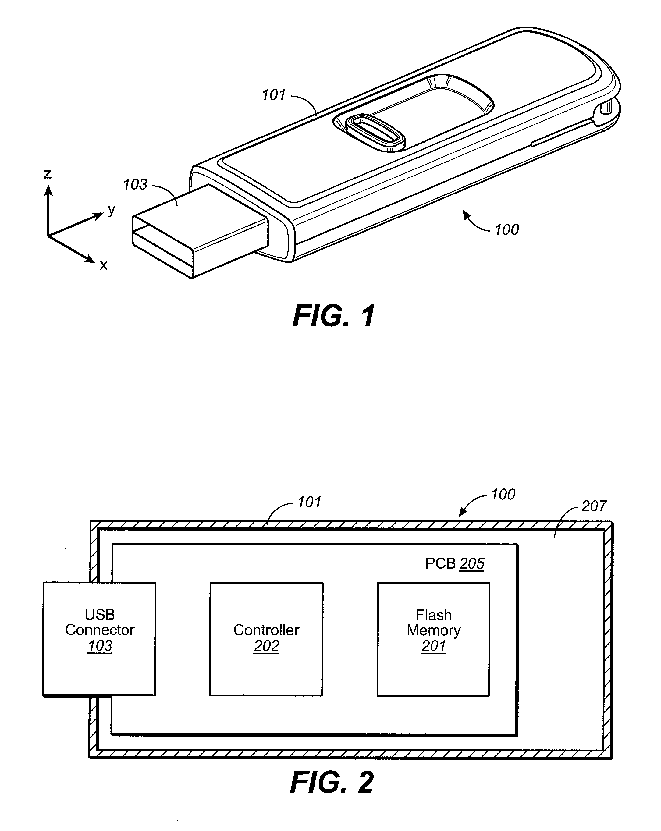
[0018]FIG. 1 shows an example of a removable flash memory unit (flash drive) 100 that has a retractable USB connector 103 extending from a housing 101. Housing 101 is made of a conductive metal in the present example (for example, a Copper alloy or steel). Housing 101 consists of a metal top lid and a metal bottom lid joined together. Other configurations are also possible and a housing may be considered to be conductive even where it includes some insulating components. An opening in housing 101 allows connector 103 to extend from housing 101 so that it can plug into a receptacle. Suitable receptacles according to the USB standard are generally provided on personal computers and other devices.

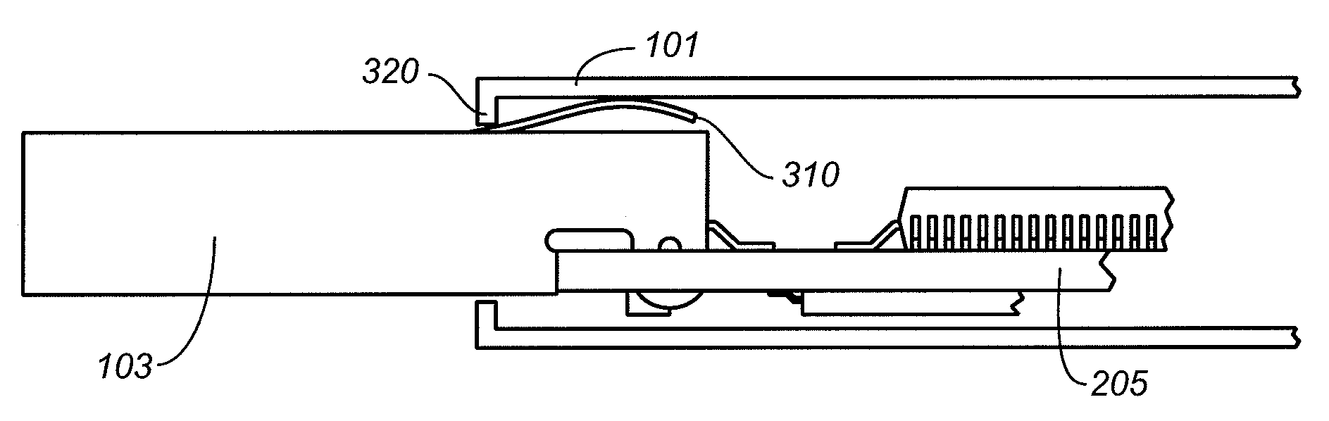
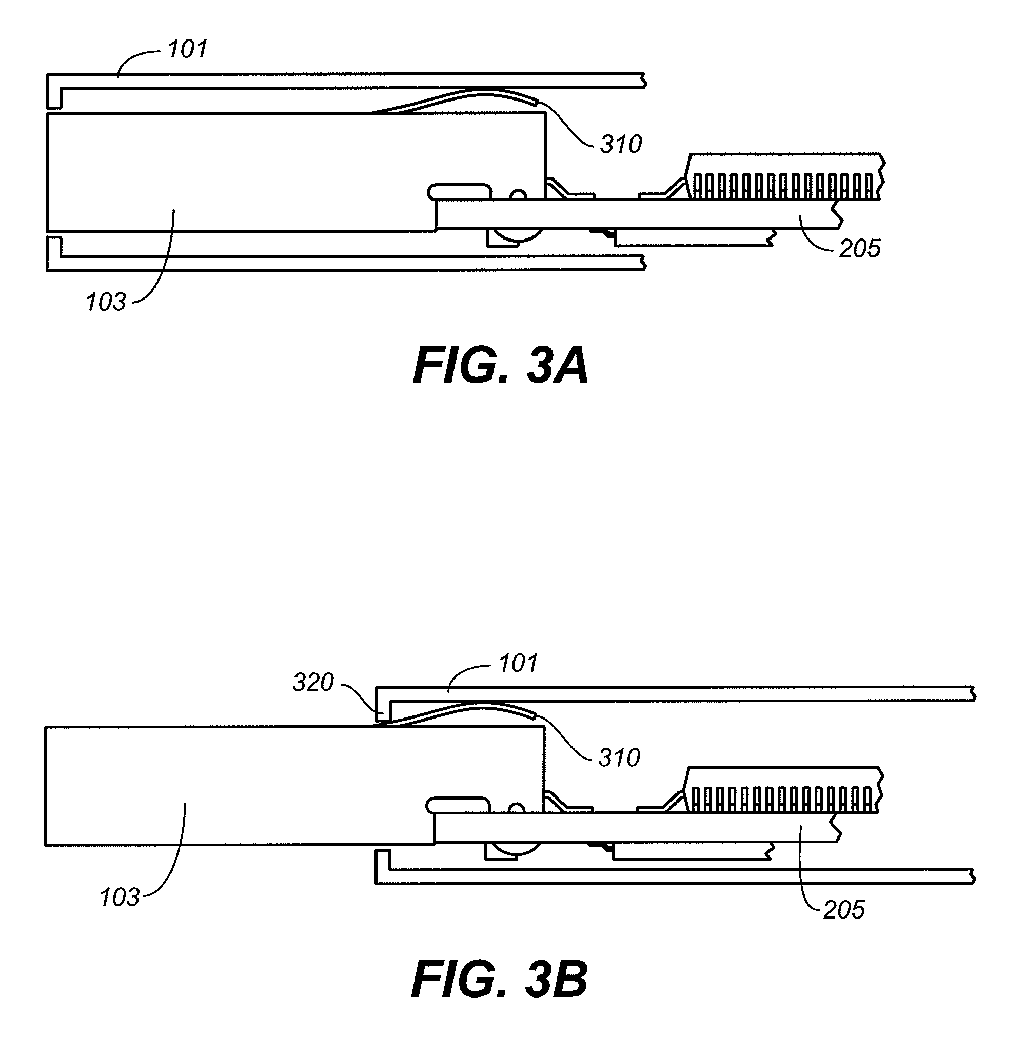
[0019]FIG. 2 shows a cross sectional view of removable flash memory unit 100 along the X-Y plane of FIG. 1. USB connector 103 is mounted to a Printed Circuit Board (PCB) 205 at one end. Also mounted to PCB 205 are a controller 202 and a memory 201. Controller 202 and memory 201 form a memory s...


PUM


Abstract

A Universal Serial Bus flash memory unit having an electrically conductive housing includes a spring that provides an electrically conductive, low-resistance pathway between the housing and the metal shell of the Universal Serial Bus connector so that electrostatic charge can directly discharge from the housing to the metal shell instead of discharging through electronic components within the housing.

Description

CROSS-REFERENCE TO RELATED APPLICATION[0001]This application is related to U.S. patent application Ser. No. ______, entitled, “Connector with ESD Protection”, filed on the same day as the present application; which application is incorporated in its entirety by reference as if fully set forth herein.BACKGROUND AND SUMMARY[0002]This invention relates generally to the use and structure of removable nonvolatile memory devices, particularly those having standardized connectors for interfacing with other electronic systems.[0003]Electronic circuit cards, including non-volatile memory cards, have been commercially implemented according to a number of well-known standards. Memory cards are used with personal computers, cellular telephones, personal digital assistants (PDAs), digital still cameras, digital movie cameras, portable audio players and other host electronic devices for the storage of large amounts of data. Such cards usually contain a re-programmable non-volatile semiconductor m...

Claims


Application Information

Patent Timeline
Patent Type & Authority Applications(United States)
IPC IPC(8): H05K1/00
CPCH05K9/0067H01R13/65802H01R13/6582
Inventor COLLANTES, PATRICIOMILLER, ROBERT C.SPROUSE, STEVEN T.PARIKH, DHAVAL
Owner SANDISK TECH LLC
Why Eureka
Try Eureka