Diffractive optical relay and method for manufacturing the same
a technology of diffractive optical relays and optical relays, applied in the field of planar optics, can solve the problems of poor light transmission efficiency, low transmission loss, and poor optical properties of optical devices made of such materials
- Summary
- Abstract
- Description
- Claims
- Application Information
AI Technical Summary
Benefits of technology
Problems solved by technology
Method used
Image
Examples
example 1
A Detailed Manufacturing Process
[0218]FIGS. 7A-L illustrate an exemplified embodiment for manufacturing the optical relay device according to the teachings of the present invention.
[0219]FIG. 7A schematically illustrates second substrate 218, which is preferably used for manufacturing the master substrate as further detailed hereinabove.
[0220]FIG. 7B schematically illustrates second substrate 218, once layer 220 of photoresist material is applied thereon.
[0221]FIG. 7C schematically illustrates second substrate 218, once pattern 222 is recorded on layer 220FIG. 7D schematically illustrates second substrate 218, once the photoresist is developed to form mask pattern 224 on layer the surface of substrate 218.
[0222]FIG. 7E schematically illustrates substrate 218 following the etching process which forms the inverted shape 202 of the grating on substrate 218.
[0223]FIG. 7F schematically illustrates substrate 218 following once mask pattern 224 is removed.
[0224]FIG. 7G schematically illust...
example 2
Birefringence Tests
[0230]Measurements of optical birefringence were made to samples of polycarbonate (PC) and cycloolefin polymer (COP). The measurements were made by the PROmeteus MT-200 inspection system purchased from Dr. Schenk GmbH, Germany. The measurements included the difference Δn between the ordinary index of refraction, no and the extra-ordinary index of refraction ne, Δn=no−ne.
[0231]FIGS. 8A-B show Δn as a function of the position x (in millimeters) across a material sample, for the polycarbonate sample (FIG. 8A) and the cycloolefin polymer (FIG. 8B).
[0232]The PC measurement revealed birefringence of about −100 nm, in the units of measurement of the measuring system, which correspond to a dimensionless birefringence Δn of about 0.001.
[0233]The COP birefringence measurement was less than 15 nm, in the units of measurement of the measuring system, which correspond to a dimensionless birefringence Δn which is no more than 0.00015 (Δn≦0.00015). It is therefore demonstrated t...
example 3
Monochromatic Binocular Configuration for Blue Light
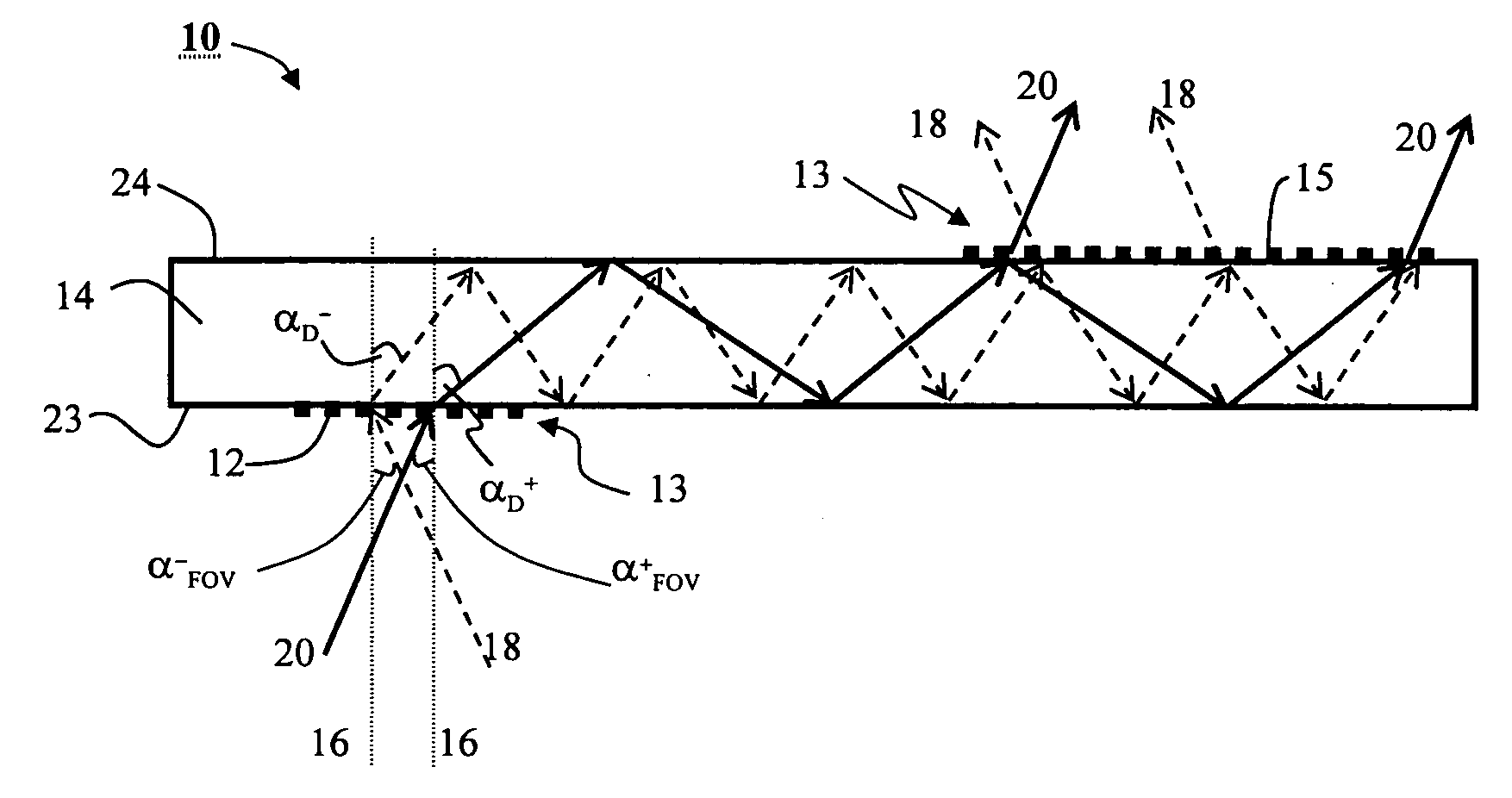
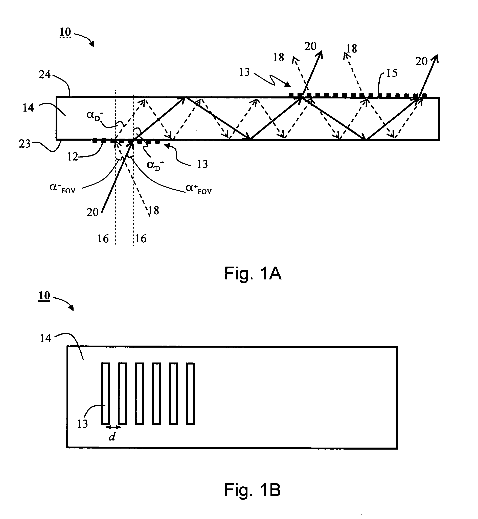
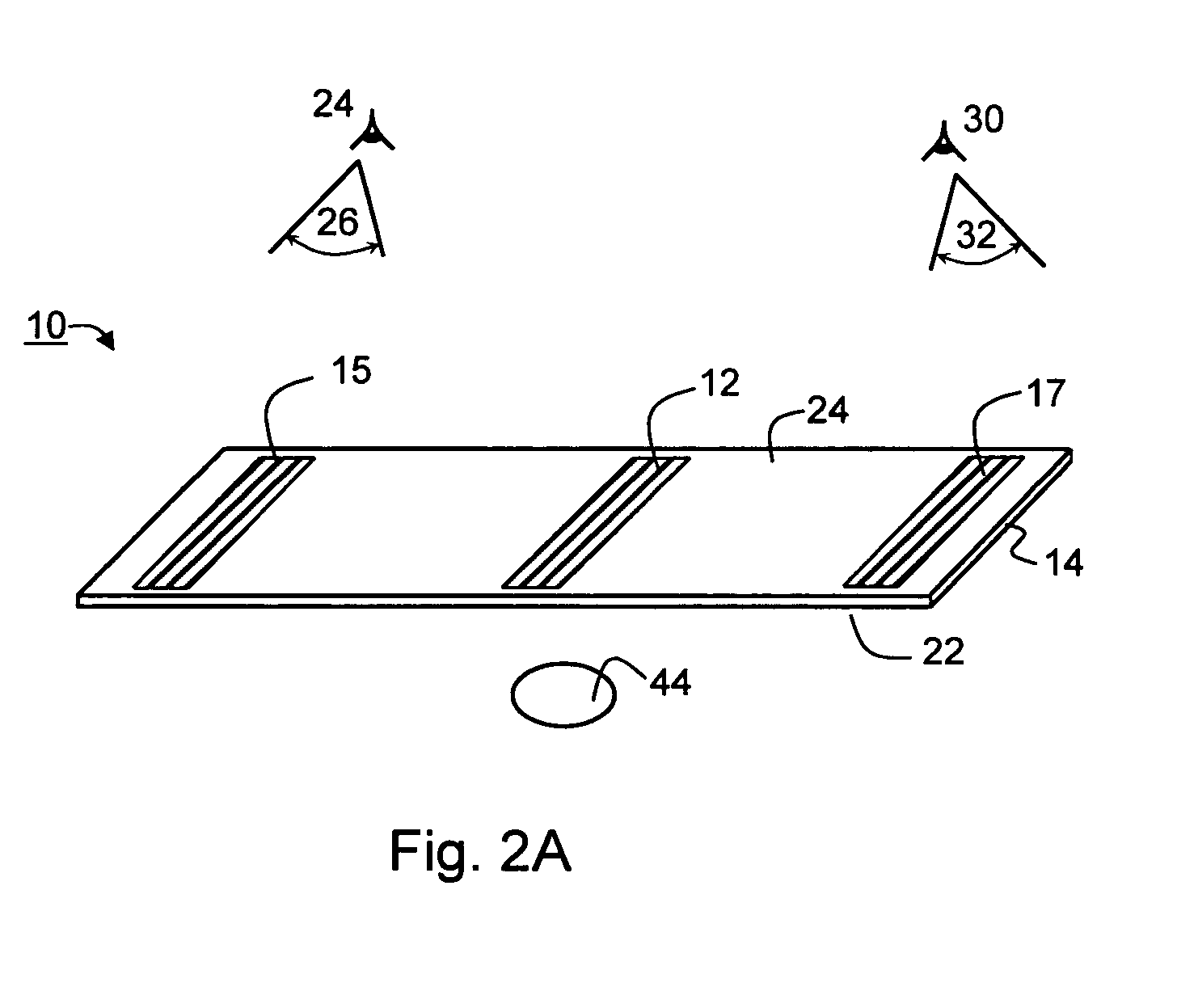
[0235]This example demonstrate the attainable field-of-view when the optical relay device is used for binocular view, in the embodiment in which there is one input linear grating and two output linear gratings. The following demonstration is for a substrate made of cycloolefin polymer having a refraction index of nS=1.531.
[0236]Equation 1 is employed for a wavelength λ=465 nm (blue light), and indices of refraction nS=1.531 for the substrate and nA=1.0 for air, corresponding to a critical angle of 40.78°.
[0237]For a grating period d=430 nm (λ / d>1, see Equation 5), Equation 2 provides the maximal (negative by sign) angle at which total internal reflection can be occur is 4.67°. In the notation of FIG. 3A, αI+−=−4.67° (see ray 53). The positive incidence angle (see ray 51 of FIG. 3A), on the other hand, can be as large as αI−−=25.24°, in which case the diffraction angle is about 80°, which comply with the total internal reflection co...
PUM
 Abstract
Description
Claims
Application Information
 - R&D
- Intellectual Property
- Life Sciences
- Materials
- Tech Scout
- Unparalleled Data Quality
- Higher Quality Content
- 60% Fewer Hallucinations
Browse by: Latest US Patents, China's latest patents, Technical Efficacy Thesaurus, Application Domain, Technology Topic, Popular Technical Reports.
© 2025 PatSnap. All rights reserved.Legal|Privacy policy|Modern Slavery Act Transparency Statement|Sitemap|About US| Contact US: help@patsnap.com


