System For Measurement Of Projected Turbulence Downwind Of An Aircraft

a technology for aircraft and turbulence, applied in the direction of instruments, ict adaptation, reradiation, etc., can solve the problems of not being able to obtain a total deflection of the surface, the distance between the nose and the wings cannot allow a phase advance of more than 100 ms, etc., to reduce the mass of the aircraft structure, reduce the fatigue load, and reduce the sizing charge

Inactive Publication Date: 2008-02-21
AIRBUS OPERATIONS (SAS)
View PDF8 Cites 27 Cited by
  • Summary
  • Abstract
  • Description
  • Claims
  • Application Information

AI Technical Summary

Benefits of technology

[0029] The system of the invention provides a number of advantages:
[0038] to improve passenger comfort: in this context, the response characterised by the accelerations of responsive body modes is reduced, so that even when minor turbulence is encountered, the passengers are not disturbed by the vibrations.

Problems solved by technology

However, even on the largest airplanes the distance between its nose and its wings does not allow for a phase advance of more than 100 ms.
With the output speed cf current actuators, it is not possible to obtain a total deflection of the surfaces, and consequently optimal efficacy in particular of the laws that reduce the loads or increase passenger comfort.

Method used


Image

  • System For Measurement Of Projected Turbulence Downwind Of An Aircraft
  • System For Measurement Of Projected Turbulence Downwind Of An Aircraft
  • System For Measurement Of Projected Turbulence Downwind Of An Aircraft

Examples


Embodiment Construction

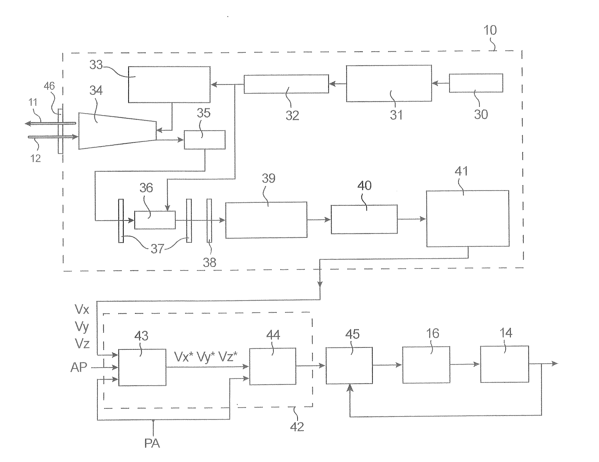
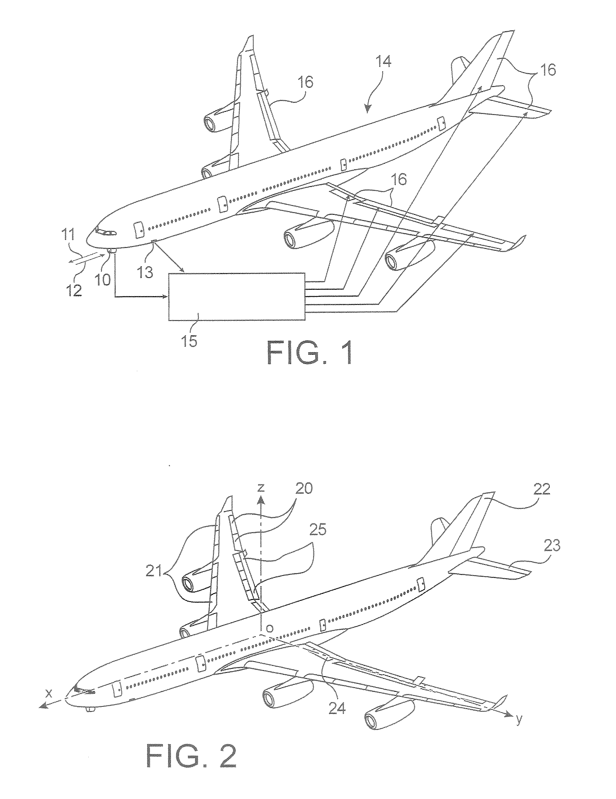
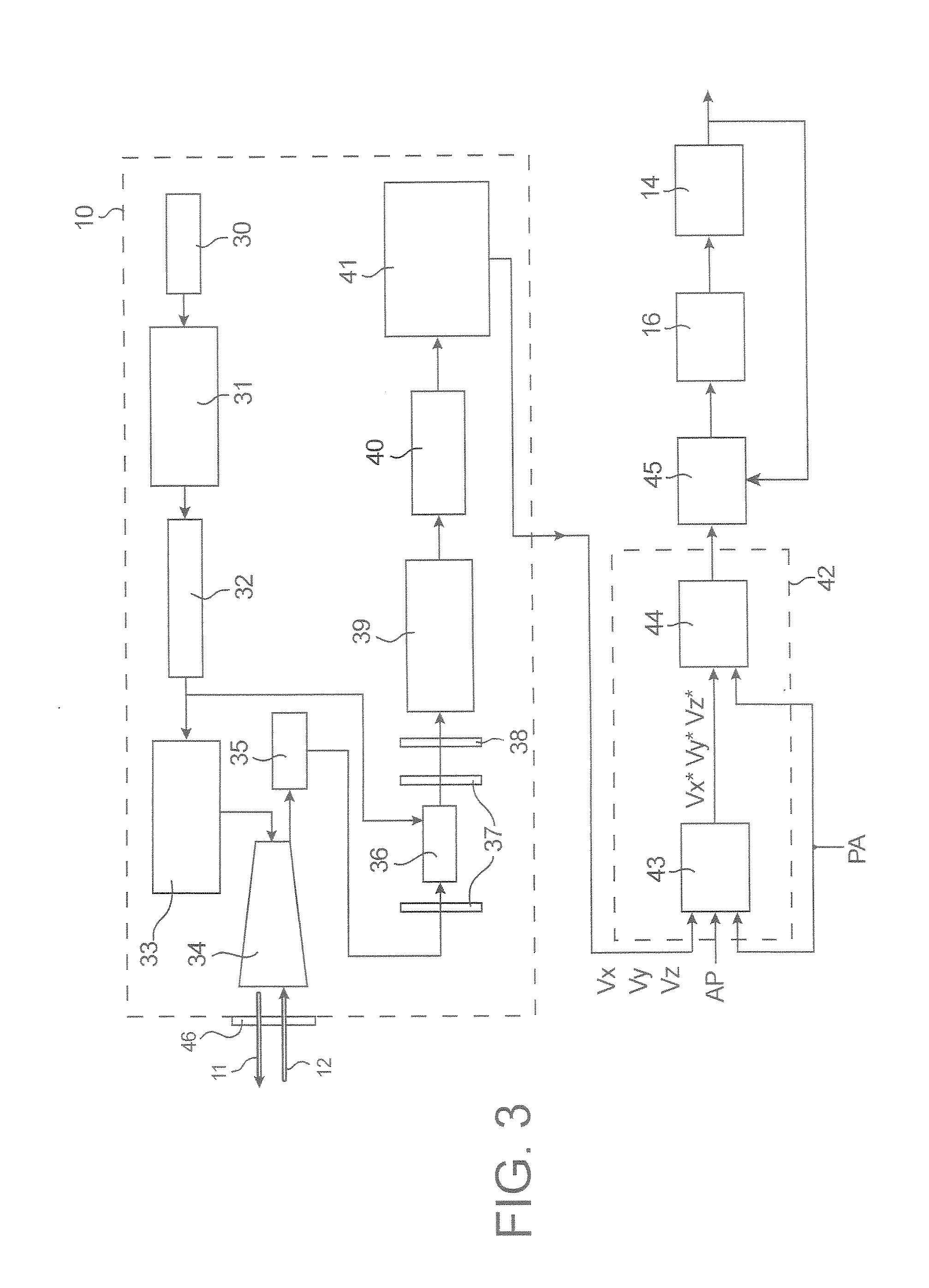
[0046] As shown in FIG. 1, in the system of the invention, the signals issued by a lidar 10, which transmits a laser beam 11 forward and receives the backscattered beam 12, as well as signals issued by sensors 13 of the airplane 14, are entered into the flight control computers 15, which give the orders to the flight control surfaces 16.

[0047] As shown in FIG. 2, these flight control surfaces 14 can thus be:

[0048] the wings 20, which are control surfaces for roll or lateral control, which give a moment with respect to the axis Ox (airplane axis),

[0049] the leading edge flaps 21, which are used at take-off and approach to back up the stall position of the wings,

[0050] the rudder 22, which is a yaw control surface or a rudder, which gives a moment with respect to the axis Oz,

[0051] the elevators 23, which are pitch control surfaces or elevators, which give a moment with respect to the axis Oy,

[0052] the “spoilers”24, which are used primarily at larding to keep the airplane on th...


PUM

PropertyMeasurementUnit
distanceaaaaaaaaaa
distanceaaaaaaaaaa
optical transmissionaaaaaaaaaa

Abstract

A system for anticipated measurement of turbulence upstream of an aircraft, placed on-board the aircraft. A lidar transmits an optical beam toward the front of the aircraft and receives the backscattered optical beam. A direct detection device is associated with a controller. A first processing component uses a first internal correction algorithm, and a second processing component uses a second external correction algorithm delivering possible command signals to actuators of at least one aircraft control surface.

Description

TECHNICAL FIELD [0001] This invention relates to a system for anticipated measurement of turbulence upstream of an aircraft. [0002] Throughout the remainder of the description the aircraft will, by way of example, be considered to be an airplane. PRIOR ART [0003] In passenger airplanes with more than 100 seats, the means for minimising the effects of turbulence are based on sensors that measure the response of the airplane once it has entered the turbulence or that make it possible to estimate the components of the wind when it reaches the airplane. The minimisation of the effects of turbulence is usually achieved by reducing the factors of load and angular speeds of the airplane subjected to turbulent conditions, reducing the structural vibrations caused, so as to improve the comfort of passengers and, finally, reducing the stresses applied to the structure of the airplane. Measurement means located on the nose of the airplane make it possible to have a phase advance with respect t...

Claims


Application Information

Patent Timeline
Patent Type & Authority Applications(United States)
IPC IPC(8): G01N21/84G01N21/01G01S17/95G05D1/06
CPCG01S17/95Y02A90/10
Inventor MIRAND, PIERRELACABANNE, MICHELAVERSA, NICKY
Owner AIRBUS OPERATIONS (SAS)
Why Eureka
Try Eureka