
Method and Apparatus for Compensating Image Sensor Lens Shading

a technology of image sensor and lens shading, which is applied in the field of method and apparatus for compensating the lens shading phenomenon of image sensor, can solve the problems of image distortion of conventional image sensor on recently marketed portable devices and degradation of original image quality, and achieve the effect of reducing signal amplitud

Active Publication Date: 2008-02-21
MILA CO LTD
View PDF16 Cites 39 Cited by
  • Summary
  • Abstract
  • Description
  • Claims
  • Application Information

AI Technical Summary

Benefits of technology

[0009] Therefore, it is an object of the invention to solve the problems described above and to provide a method and apparatus for compensating the lens shading phenomenon in image sensor which prevent degradation of original image.
[0012] It is another object of the invention to provide a method and apparatus for compensating the lens shading phenomenon in image sensor in which the amount of data to be processed can be minimized when correcting the original image.

Problems solved by technology

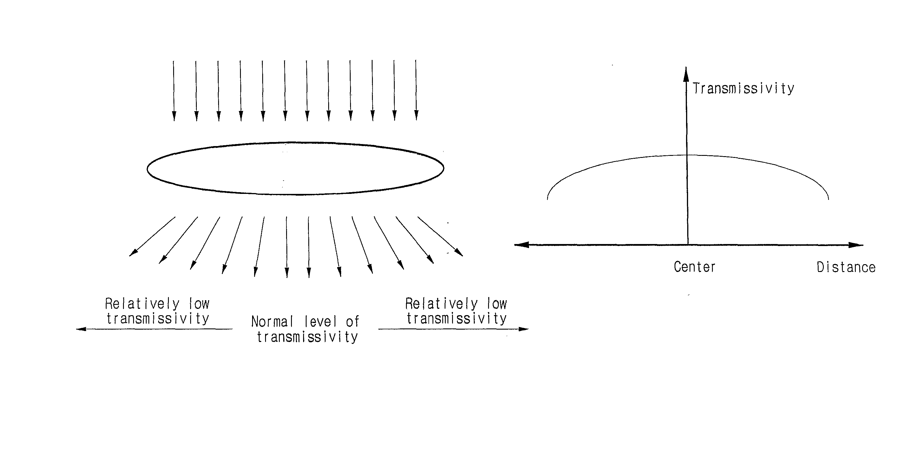
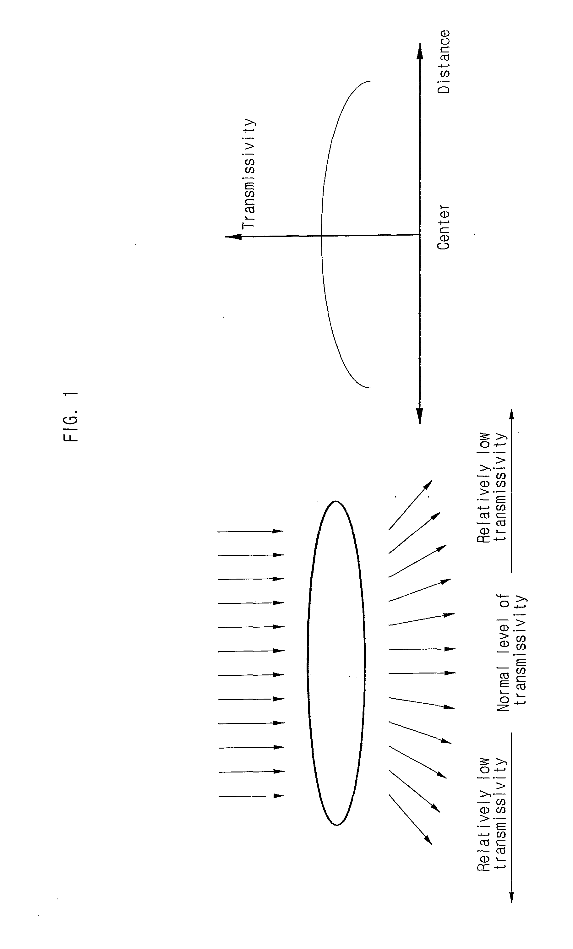
However, the conventional image sensor on recently marketed portable devices had a problem of image distortion due to the geometric pattern of the pixel array composition.
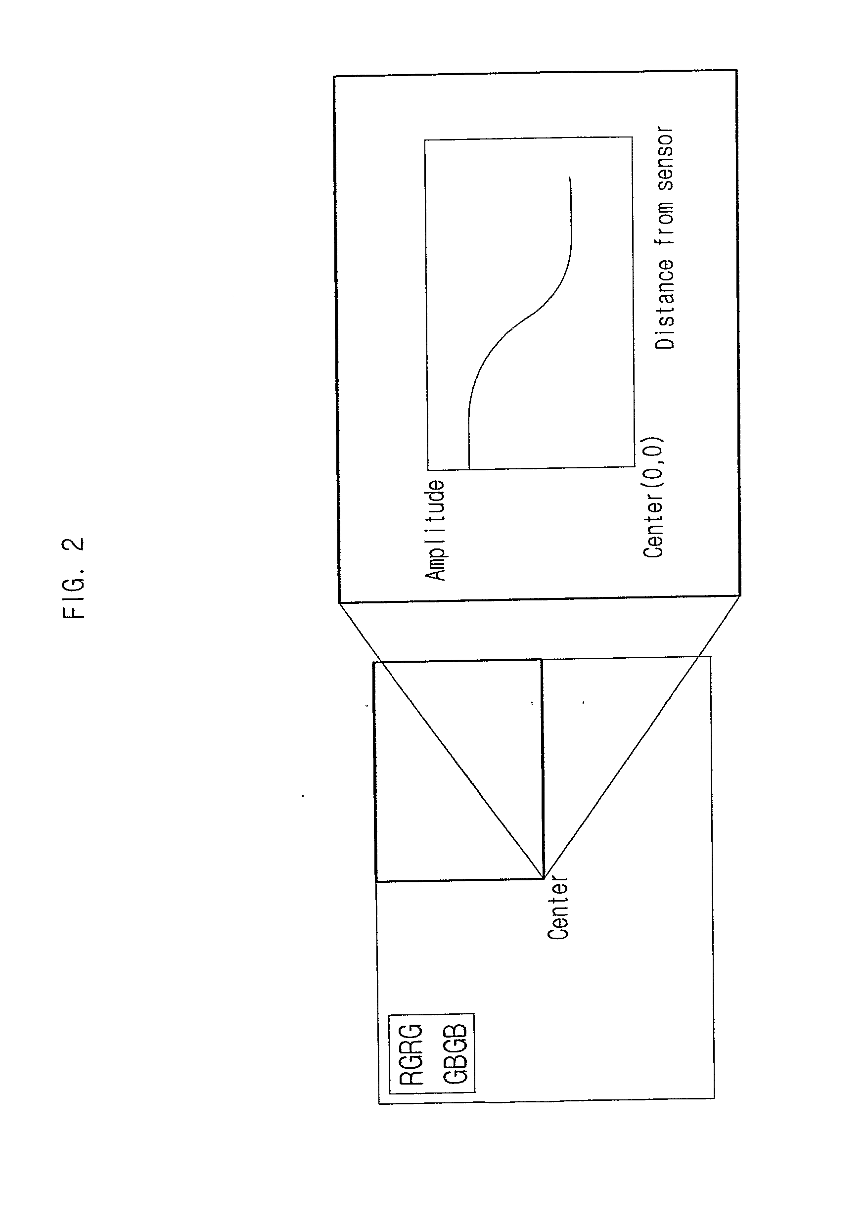
Consequently, color distortion and reduction in signal amplitude dependant on the position of the pixels inevitably occur, which cause degradation in the quality of original images.

Method used


Image

  • Method and Apparatus for Compensating Image Sensor Lens Shading
  • Method and Apparatus for Compensating Image Sensor Lens Shading
  • Method and Apparatus for Compensating Image Sensor Lens Shading

Examples


embodiments

[0044] To fully understand the invention, the operational advantages of the invention, and the objectives realized through the use of the invention, the accompanying drawings and the description included therein must be examined which illustrate preferred embodiments of the invention.

[0045] Hereinafter, preferred embodiments of the invention will be described in more detail with reference to the accompanying drawings. In the descriptions, identical components are rendered the same reference number regardless of the figure number to allow an overall understanding of the invention.

[0046]FIG. 3 is a schematic illustrating the composition of an imaging device according to the preferred embodiment of the invention.

[0047] Referring to FIG. 3, the imaging device 100 according to the invention comprises a sensor 110, an image processor 125, and a display 110. Of course, an input key or memory etc. may further be included, but explanation on these components is omitted, as they are irrele...


PUM

PropertyMeasurementUnit
Distanceaaaaaaaaaa
Brightnessaaaaaaaaaa
Luminanceaaaaaaaaaa

Abstract

The invention relates to a method and apparatus for compensating the lens shading phenomenon in image sensor. The invention first stores an inputted compensation reference value, identifies a center pixel using digital image signals received sequentially in correspondence to each pixel from a sensor, generates analysis data corresponding to each pixel, generates and stores block compensation values for blocks grouped according to the distance from the center pixel, calculates the distance from a compensation target pixel to the center pixel, calculates a compensation value corresponding to the compensation target pixel using the block compensation value corresponding to the distance, and generates for output correction pixel data by aggregating analysis data and the compensation value corresponding to the compensation target pixel. Thus, the invention allows the maintaining of colors as close as possible to the original through the respective compensation of RGB which takes into consideration the respective characteristics of the color filters and through the respective compensation of gain and level for the disparity in transmissivity according to position.

Description

FIELD OF THE INVENTION [0001] The invention relates to a method and apparatus for compensating the lens shading phenomenon in image sensor, more particularly to a method and apparatus for compensating the lens shading phenomenon in image sensor where the quality of original images is maintained by correcting the reduction in signal amplitude according to the position of the pixels. BACKGROUND OF THE INVENTION [0002] Portable devices with image sensor (e.g. digital cameras, mobile communication terminals, etc.) have recently been developed and are currently in the market. Image sensor comprises an array of tiny photosensitive diodes known as pixels or photosites. The pixels themselves usually do not extract color from light, but convert photons into electrons from a wide spectrum band. To record color images with a single sensor, the sensor is filtered so that different pixels receive lights with different colors. This type of sensor is known as a color filter array, or CFA. Differen...

Claims


Application Information

Patent Timeline
IPC IPC(8): H04N9/73C12N9/02C12N15/82C12P17/18H04N5/217
CPCC12N9/0071H04N5/217C12P17/181C12N15/8243H04N23/81H04N25/61H04N23/75H04N25/00
Inventor KIM, DONG-YONGNOH, YO-HWAN
Owner MILA CO LTD
Learn More