
Apparatus, System and Method for Reducing Acoustic Feedback Interference Signals

Active Publication Date: 2017-06-08
EARGO
View PDF5 Cites 5 Cited by
  • Summary
  • Abstract
  • Description
  • Claims
  • Application Information

AI Technical Summary

Benefits of technology

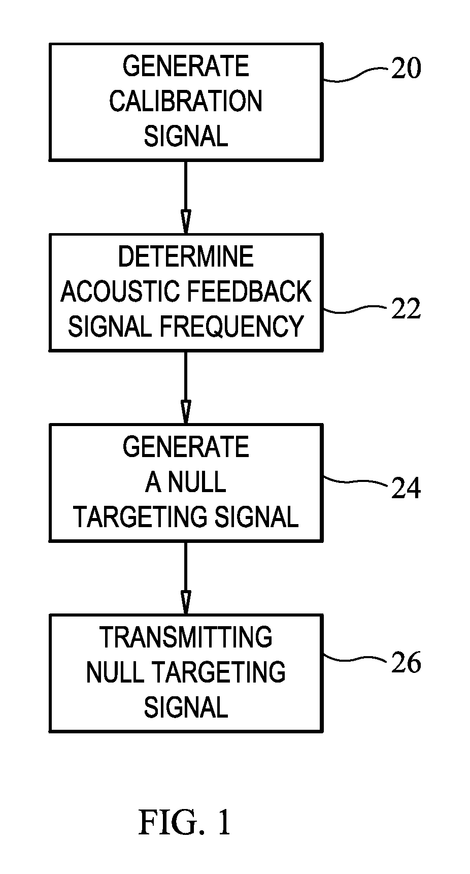
The patent is about a way to reduce feedback in a hearing aid by using a null-steering microphone and a null targeting signal. The system detects sound and sends signals to a sound processor. The processor then sends out a targeting signal to help reduce the feedback. This results in less feedback to the receiver, making it easier to hear the detected sound.

Problems solved by technology

However, there is a limit to the amount of sound isolation that any ear mold can provide; even with the tightest mold; given enough amplification, sound is going to leak from the ear canal and will start the feedback cycle.
However, since acoustic feedback is often a complex signal (like a tone with a series of harmonics), the cancellation process requires a complex solution, since more than one frequency is involved.
Thus, a disadvantage to this technique is that digital processing methods often eliminate desirable acoustic signals along with the acoustic feedback signal resulting in transmitted audio signal distortion.

Method used


Image

  • Apparatus, System and Method for Reducing Acoustic Feedback Interference Signals
  • Apparatus, System and Method for Reducing Acoustic Feedback Interference Signals
  • Apparatus, System and Method for Reducing Acoustic Feedback Interference Signals

Examples


Embodiment Construction

[0055]Before describing the present invention in detail, it is to be understood that this invention is not limited to particularly exemplified apparatus, systems, structures or methods as such may, of course, vary. Thus, although a number of apparatus, systems and methods similar or equivalent to those described herein can be used in the practice of the present invention, the preferred apparatus, systems, structures and methods are described herein.

[0056]It is also to be understood that the terminology used herein is for the purpose of describing particular embodiments of the invention only and is not intended to be limiting.

[0057]Unless defined otherwise, all technical and scientific terms used herein have the same meaning as commonly understood by one having ordinary skill in the art to which the invention pertains.

[0058]Further, all publications, patents and patent applications cited herein, whether supra or infra, are hereby incorporated by reference in their entirety.

[0059]Fina...


PUM


Abstract

Apparatus, systems and methods for reducing feedback in a hearing aid that includes a transducer configured to detect sound, a sound processor configured to process signals from the transducer, a receiver configured to receive signals outputted from the sound processor, and an acoustic feedback reduction system. The acoustic feedback reduction system is configured to provide signals to the sound processor to produce a null targeting signal steerable toward a source of feedback.

Description

CROSS-REFERENCE[0001]This application claims the benefit of U.S. Provisional Application No. 62 / 246,583, filed on Dec. 8, 2015, which application is hereby incorporated herein, in its entirety, by reference thereto, and to which we claim priority under 35 U.S.C. Section 119.[0002]This application also hereby incorporates the following U.S. Patent Applications and their corresponding patents herein, in their entireties, by reference thereto: U.S. patent application Ser. No. 15 / 195,100, filed Jun. 28, 2016; U.S. application Ser. No. 14 / 032,310, filed Sep. 20, 2013; U.S. application Ser. No. 13 / 865,717, filed Apr. 18, 2013, now U.S. Pat. No. 8,577,067; U.S. application Ser. No. 12 / 841,120, filed Jul. 21, 2010, now U.S. Pat. No. 8,457,337; U.S. Provisional Application No. 61 / 228,571, filed Jul. 27, 2009; U.S. Provisional Application No. 61 / 228,588, filed Jul. 26, 2009; and U.S. application Ser. No. ______ (Application Serial No. has not yet been assigned, Attorney's Docket No. EARG-001C...

Claims


Application Information

Patent Timeline
IPC IPC(8): H04R25/00
CPCH04R25/453H04R25/405H04R25/505H04R2460/09H04R25/402H04R2225/025H04R2201/003H04R2201/401H04R2201/403H04R2201/405
Inventor HERSCHER, BRETUNNO, TAKAHIROSHEN, DANIELMICHEL, FLORENTMICHEL, RAPHAEL
Owner EARGO
Learn More