
Method and system for operating a laser self-modulated at alkali-metal atom hyperfine frequency

a laser and hyperfine frequency technology, applied in the field of pulse laser systems, optically pumped atomic magnetometers, optically pumped atomic clocks, etc., can solve the problems of reducing the utility of miniature atomic clocks, reducing the battery life, and cpt methods with fixed circularly polarized light and fm modulation suffer from the effects, so as to improve the performance of cpt atomic clocks and boost the cpt signal

Inactive Publication Date: 2008-02-21
PRINCETON UNIV
View PDF3 Cites 10 Cited by
  • Summary
  • Abstract
  • Description
  • Claims
  • Application Information

AI Technical Summary

Benefits of technology

"The present invention provides a method and apparatus for operating atomic clocks or magnetometers without a local oscillator and without an electronic feed-back loop for stabilizing the local-oscillator frequency. The atomic-clock signal is directly obtained from self-modulated laser light using a push-pull optical pumping technique. The method and system are based on the physics of a push-pull optical pumping technique using an alkali-metal vapor cell placed inside a laser cavity to modulate the laser light. The invention solves the problem of conventional CPT by boosting up the CPT signal by a significant factor and effectively improving the performance of CPT atomic clocks."

Problems solved by technology

The conventional CPT method with fixed circularly polarized light and FM modulation suffers from the effects of population dilution and high buffer-gas pressure.
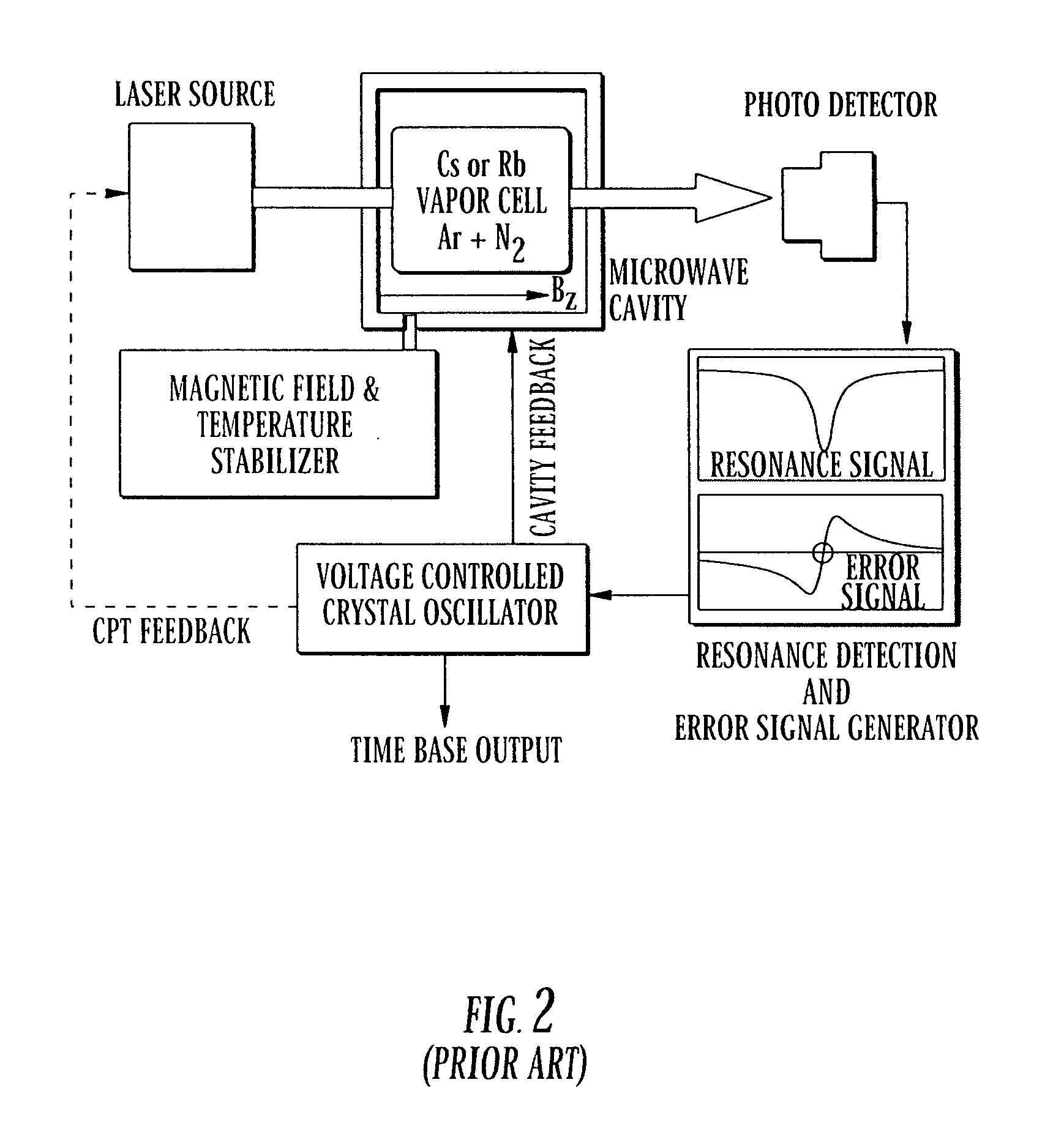
As for the power consumption of a conventional passive atomic clock, the local oscillator and the microwave circuitry can be a major draining source because of the complexity of the microwave circuitry and feedback loops of the passive-type atomic clocks.
For a portable atomic-clock device, relatively high power consumption can reduce the battery lifetime and therefore decrease the utility of the miniature atomic clock.

Method used


Image

  • Method and system for operating a laser self-modulated at alkali-metal atom hyperfine frequency
  • Method and system for operating a laser self-modulated at alkali-metal atom hyperfine frequency
  • Method and system for operating a laser self-modulated at alkali-metal atom hyperfine frequency

Examples


Embodiment Construction

[0026] Reference will now be made in greater detail to a preferred embodiment of the invention, an example of which is illustrated in the accompanying drawings. Wherever possible, the same reference numerals will be used throughout the drawings and the description to refer to the same or like parts.

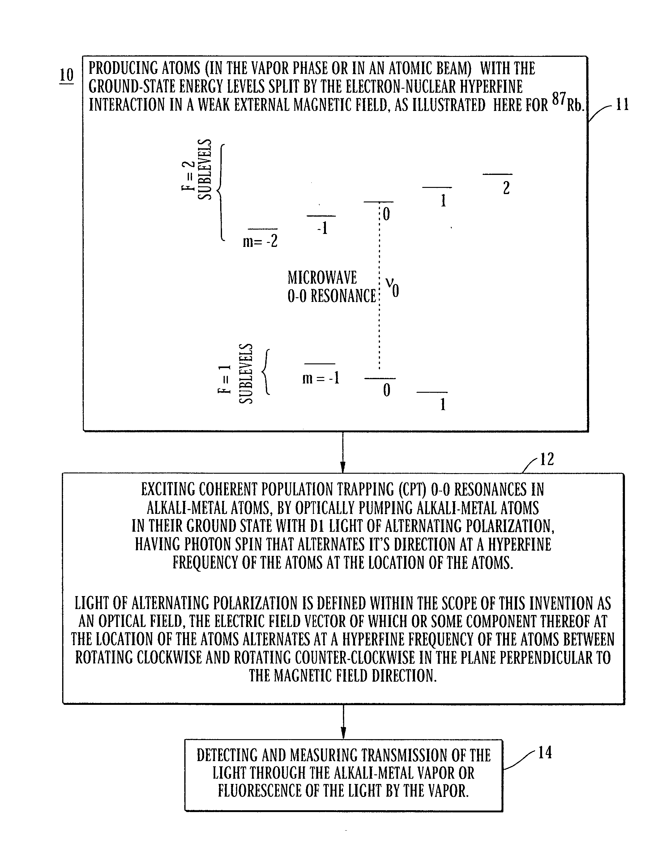
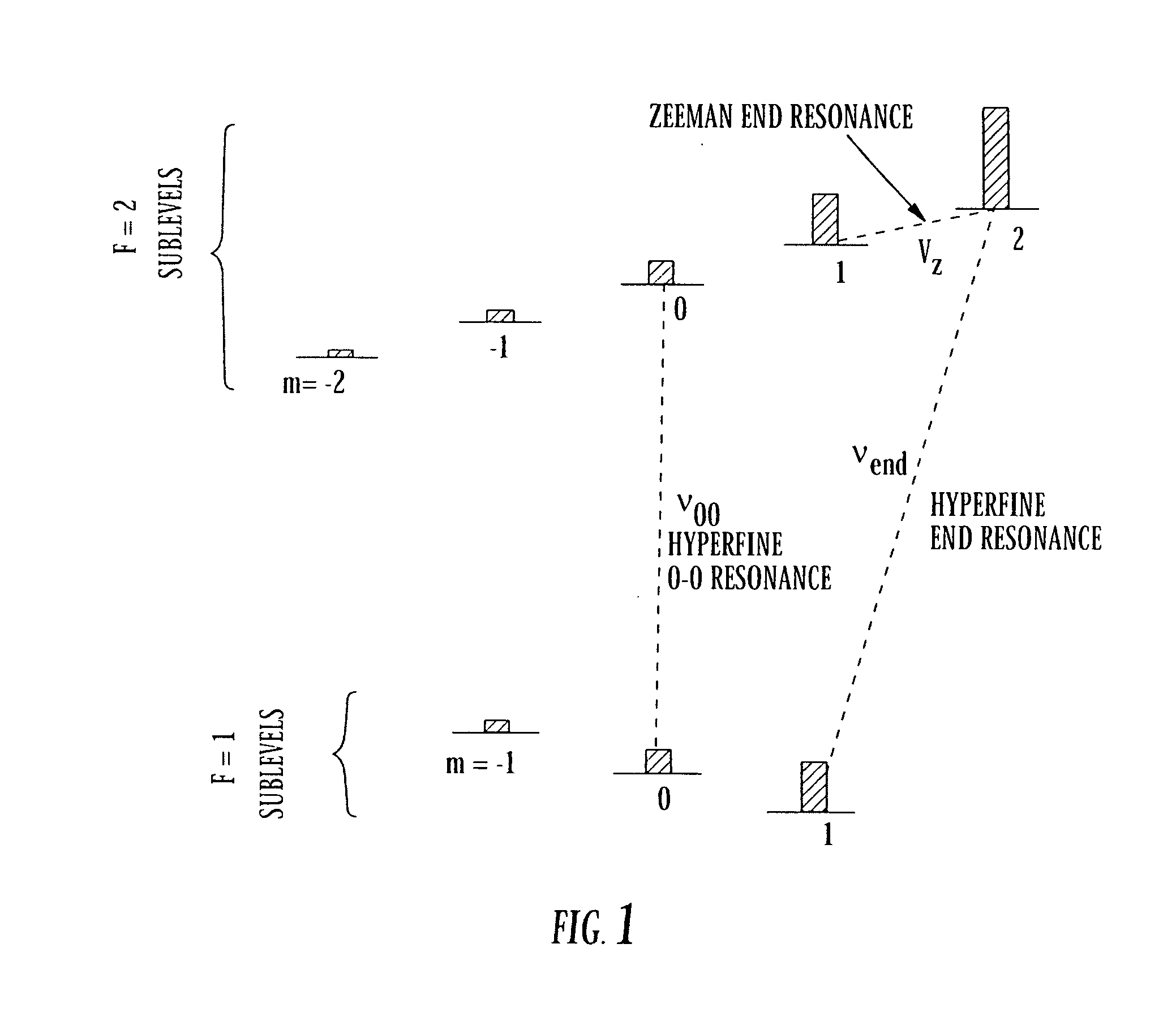
[0027]FIG. 3 is a flow diagram of a method for operating an atomic clock or magnetometer 10 using a push pull pumping technique in accordance with the teachings of the present invention. In block 11, atoms are generated in a vapor phase or in an atomic beam, their ground state split by the electron-nuclear hyperfine interaction. The atomic vapor can be mixed with a buffer gas or gases, such as nitrogen or any of the noble gases, or a mixture thereof. A weak external magnetic field is needed to define the quantization direction at the location of the atoms. The quantum numbers F and m are used to label the ground-state sublevels of the alkali-metal atom. Here F is a quantum number of the ...


PUM


Abstract

The present invention provides a method and apparatus for making atomic clocks or atomic magnetometers as self-modulated laser systems based on the physics of push-pull optical pumping. An atomic vapor cell is required to be in the laser cavity. With proper conditions, spontaneous push-pull optical pumping can occur inside the laser cavity. This causes the laser beam to be modulated at hyperfine-resonance frequency. With a fast photodetector, the modulated laser signal can be converted into the electrical signal, which serves as the atomic clock ticking signal or magnetometer signal. The self-modulated laser system does not use any local oscillator and the microwave circuit to lock the oscillator frequency to the hyperfine-resonance frequency, and therefore can consume less power and become more compact than conventional systems. This invention will benefit applications of time measurements and magnetic-field measurements.

Description

CROSS REFERENCE TO RELATED APPLICATION [0001] This application is a continuation-in-part of U.S. patent application Ser. No. 11 / 052,261 filed Feb. 7, 2005, claiming priority to U.S. Provisional Application No. 60 / 545,359, filed on Feb. 18, 2004, and this application claims priority to U.S. Provisional Application No. 60 / 630,024, filed on Nov. 22, 2004, the disclosure of each application is hereby incorporated by reference in its entirety.STATEMENT OF GOVERNMENT FUNDED RESEARCH [0002] This work was supported by the Air Force Office Scientific Research F49620-01-1-0297. Accordingly, the Government has certain rights in this invention.BACKGROUND OF THE INVENTION [0003] 1. Field of the Invention [0004] The present invention relates to the field of optically pumped atomic clocks, optically pumped atomic magnetometers, pulse laser systems, and more particularly to a laser that is self-modulated by alkali-metal vapor at 0-0 atomic-clock frequency by using light of alternating polarization ...

Claims


Application Information

Patent Timeline
Patent Type & Authority Applications(United States)
IPC IPC(8): H01S1/06
CPCG01R33/26H03L7/26G04F5/145
Inventor HAPPER, WILLIAMJAU, YUAN-YU
Owner PRINCETON UNIV
Learn More