Preswirl pollution air handling with tangential on-board injector for turbine rotor cooling

a technology of turbine rotor and injector, which is applied in the direction of engine components, blade accessories, machines/engines, etc., can solve the problems of blocked passages, unused passages, etc., and achieve the effect of reducing the impact and minimizing the decrease in the velocity of the discharge air

Inactive Publication Date: 2008-02-21
UNITED TECH CORP
View PDF4 Cites 51 Cited by
  • Summary
  • Abstract
  • Description
  • Claims
  • Application Information

AI Technical Summary

Benefits of technology

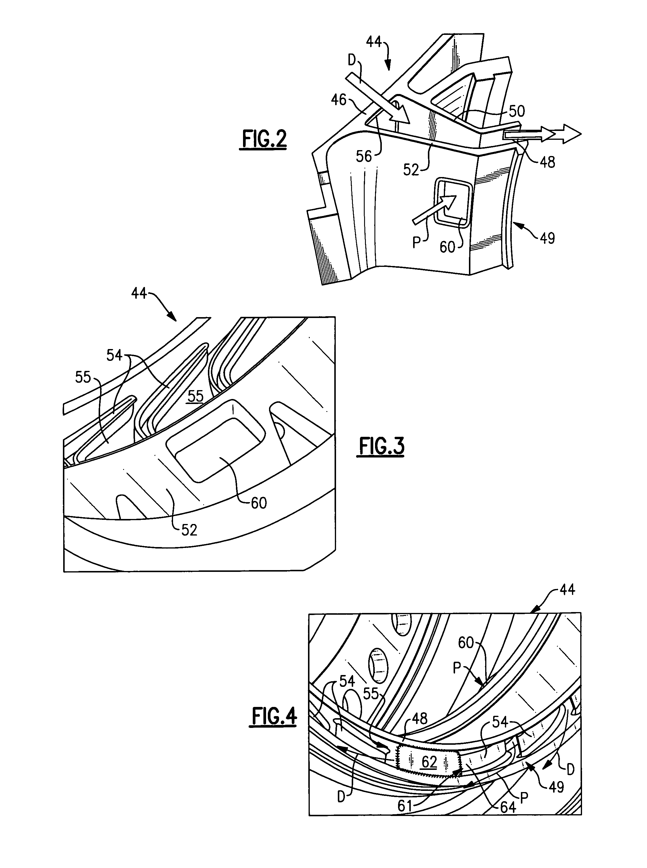
[0007]The TOBI provides multiple passages separated by vanes. At least some of the passages include discharge inlets and outlets for carrying the discharge air from the compressor to the turbine rotor. Typically, several of the passages are unused and blocked. However, the example arrangement provides a pollution inlet and outlet in at least one of the normally unused, blocked passages. The pollution

Problems solved by technology

Typically, several of the pas

Method used


Image

  • Preswirl pollution air handling with tangential on-board injector for turbine rotor cooling
  • Preswirl pollution air handling with tangential on-board injector for turbine rotor cooling
  • Preswirl pollution air handling with tangential on-board injector for turbine rotor cooling

Examples


Embodiment Construction

[0014]A turbo machine such as a gas turbine engine 10 is shown in FIG. 1. The gas turbine engine 10 includes a compressor 12 and a turbine 19 mounted on a shaft 15, which is rotatable about an axis A. In one example gas turbine engine, the compressor 12 is a high pressure compressor, and a low pressure compressor and fan respectively are located to the left of the compressor 12. The turbine 19 is a high pressure turbine, and a low pressure turbine is located to the right of the turbine 19.

[0015]The compressor 12 includes a hub 14 mounted on the shaft 15. A discharge outlet 16 expels discharge air D from the compressor 12 to a turbine inlet 20 via passages 18. A turbine hub 22 supporting blades 24 is mounted on the shaft 15. The blades 24 receive and expand the discharge air D from the turbine inlet 20.

[0016]Pollution air P is produced within the gas turbine engine 10 from fluid that leaks past various seals. For example, compressor seals 26 and 28 arranged between the hub 14 and eng...


PUM


Abstract

A gas turbine engine includes a turbine rotor and a compressor, which provides discharge air. A nozzle, typically referred to a tangential on-board injector (TOBI), is arranged near the rotor to deliver the discharge air near the turbine rotor for cooling it. The TOBI receives pollution air leaking past seals within the gas turbine engine. The TOBI swirls the discharge air and the pollution air before it reaches the turbine rotor. The TOBI provides multiple passages separated by vanes. At least some of the passages include discharge inlets and outlets for carrying the discharge air from the compressor to the turbine rotor. Typically, several of the passages are unused and blocked. However, the example arrangement provides a pollution inlet and outlet in at least one of the normally unused, blocked passages. The pollution air flowing through its passage in the TOBI is swirled so that the pollution air that intermingles with the swirled discharge air, while minimizing the reduction in velocity of the discharge air that is used to cool the turbine rotor.

Description

BACKGROUND OF THE INVENTION[0001]This invention relates to a method and apparatus of handling pollution air within a gas turbine engine. More particularly, the invention relates to swirling the pollution air prior to introducing it to discharge air from the compressor when cooling the turbine rotor.[0002]The limiting factor in most turbine designs is the maximum temperature that can be tolerated at the turbine inlet. To address this problem, inlet vanes of the first stage turbine and rotor blades are cooled typically using compressor bleed air, which is simply referred to as discharge air.[0003]Modern gas turbine engines typically incorporate a preswirl system using a nozzle referred to as a tangential on-board injector (TOBI). Swirling the air reduces the temperature rise associated with injecting cooling air on board the turbine rotor.[0004]Gas turbine engines produce pollution air, which is air that leaks past the various seals within the gas turbine engine to the TOBI. The disch...

Claims


Application Information

Patent Timeline
IPC IPC(8): F02C6/08
CPCF01D5/081F05D2260/6022F05D2260/14
Inventor MOORE, CHRISTOPHERVIRTUE, JOHN P.CHRISIKOS, JAMES P.
Owner UNITED TECH CORP
Why Eureka
Try Eureka