
Polarization-Controlled Encoding Method, Encoder, And Quantum Key Distribution System

a quantum key and encoder technology, applied in the field of secure optical communication, can solve the problems of not being able to counteract, the stability and anti-jamming ability of the system are poor, and the variation of the scheme has no essential improvement, so as to reduce the requirement of modulation rate, reduce the requirement of environmental requirements of quantum key distribution system, and improve the stability of the system.

Active Publication Date: 2008-02-14
ANHUI QASKY QUANTUM SCI & TECH CO LTD
View PDF3 Cites 37 Cited by
  • Summary
  • Abstract
  • Description
  • Claims
  • Application Information

AI Technical Summary

Benefits of technology

[0004] The present invention provides a polarization-controlled quantum key distribution encoding method, encoder and system. It can provide unconditional secure key distribution between two users.
[0018] Comparing with existing encoder bases on Mach-Zehnder interferometer, the encoder of present patent controls polarization state of optical pulse inside itself. This makes it insensitive to disturbance on itself so that the environment requirements of quantum key distribution system reduced largely. Because two pulses injected into the quantum channel are controlled at same polarization state, the disturbance they suffered when transmitting is compensated before they enter the receiver. That means signal transmitting is independent of channel disturbance. The stability of system is improved greatly. In the encoder with 90 degree Faraday mirrors according to the invention, the pulse passes through the phase modulator twice with orthogonal polarization. If the duration of phase modulating signal is larger than the time slot during which the pulse pass through modulator twice, the modulation will be independent of polarization. So the polarization-dependent modulator can be used to achieve polarization-independent modulation. The requirement of modulation rate will also be reduced. In the encoder with polarization-maintained beam splitter according to the invention, since polarization of optical pulses is maintained, polarization-dependent modulator can be used.
[0019] In quantum key distribution system according to the invention, return photon separating and detecting unit can be added to separate and detect any reverse transmitted photons. This will not only prevent spy photons from entering the encoder to eavesdrop information but also detect whether there is an eavesdropper. Since single photon detector and circulator have a certain range of response wavelength, optical band pass filter can be added in the quantum key distribution system so that optical pulses with wavelength in working spectrum can pass through the filter, pulses with wavelength out of working spectrum can not pass through the filter. This can compensate the disadvantage that single photon detector and circulator don't have enough response band.

Problems solved by technology

That's because the symmetry of normal fiber is not good and the interference in transmission path disturbs the polarization state, the photon polarization will be random changed during transmission in it.
Because the optical pulses pass through the different arms of the different interferometers in transmitter and receiver, the disturbance they suffered is not exactly identical to each other and can't be counteracted.
The stability and anti-jamming ability of the system is bad.
A lot of variations of this scheme have no essential improvement.
This is deadly for information security.

Method used


Image

  • Polarization-Controlled Encoding Method, Encoder, And Quantum Key Distribution System
  • Polarization-Controlled Encoding Method, Encoder, And Quantum Key Distribution System
  • Polarization-Controlled Encoding Method, Encoder, And Quantum Key Distribution System

Examples


first embodiment

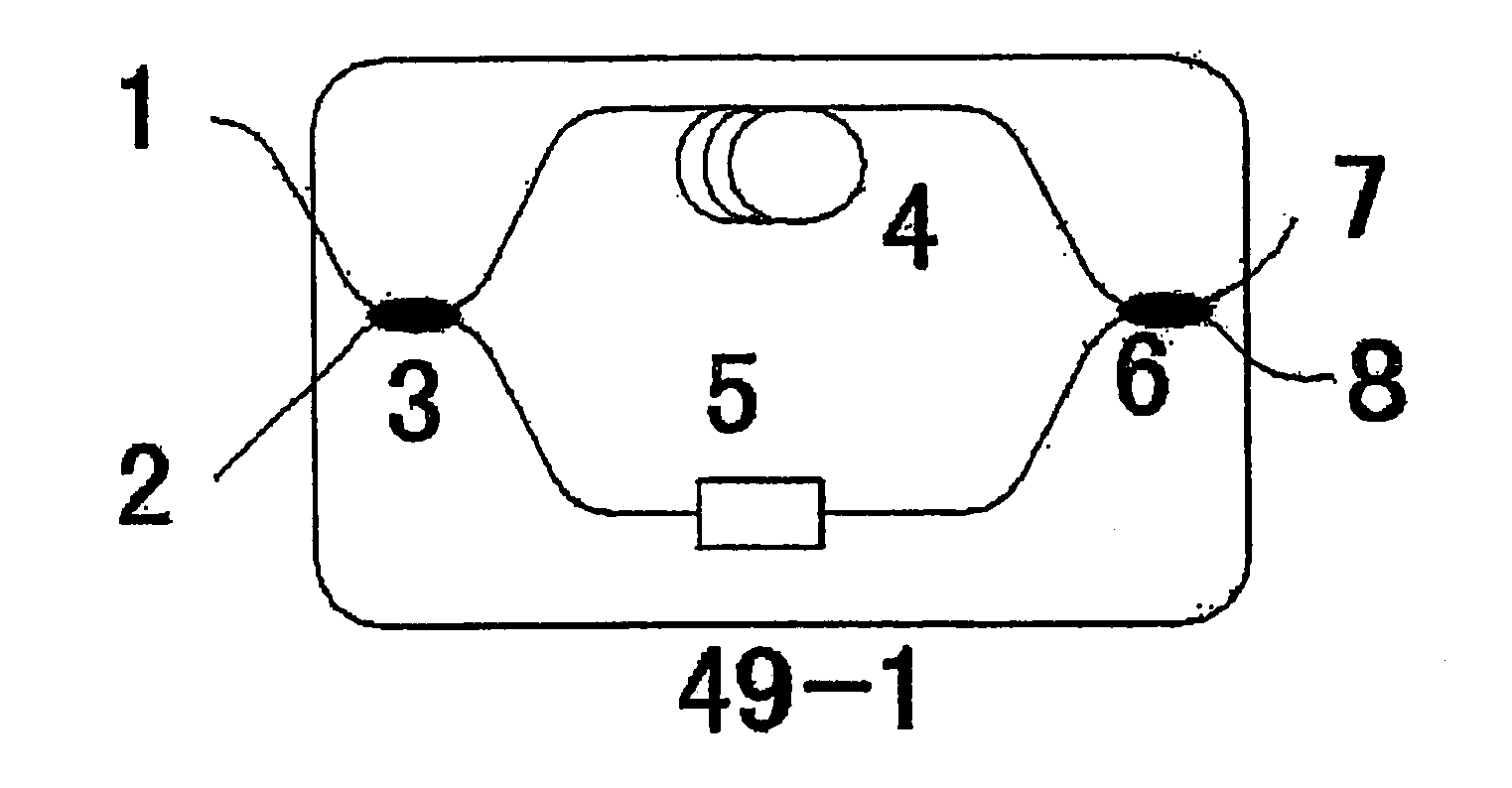
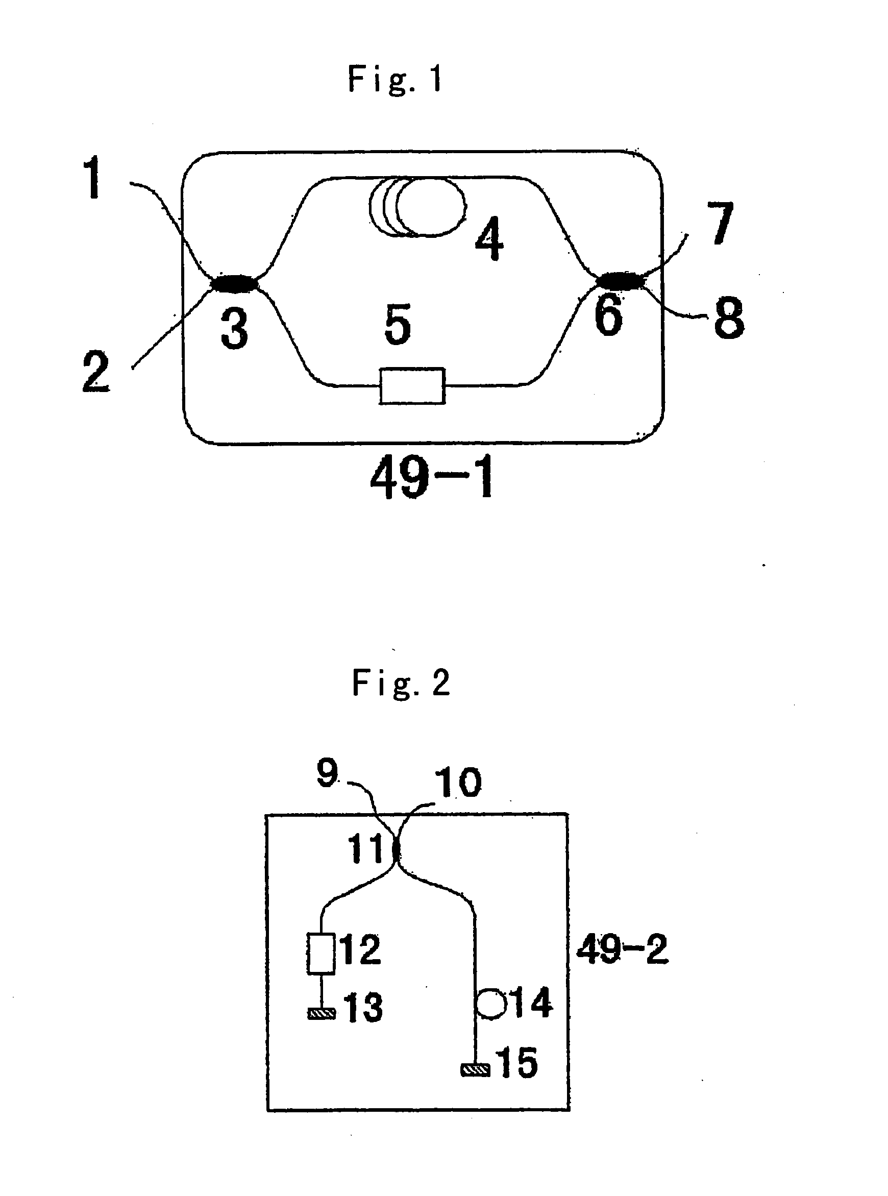
[0030] The first configuration of polarization-controlled encoder in quantum key distribution system is shown in FIG. 1. It includes two 2×2-3 dB polarization-maintained beam splitters 3 and 6, one polarization-maintained phase modulator 5 and one polarization-maintained delay line 4. These form a Mach-Zehnder interferometer. Any one of the two ports 1 and 2 which are in the same side of 3 dB beam splitter 3 can be the input port of polarization-controlled encoder. Any one of the two ports 7 and 8 which are in the same side of 3 dB beam splitter 6 can be the output port. The modulator 5 and delay line 4 (no sequencing) can be inserted into one arm of the Mach-Zehnder interferometer or two arms separately. When the system works, an optical pulse is injected into port 1 or 2 of beam splitter 3 and divided into two pulses. One pulse passes through the modulator 5. Another one pass through the delay line 4.

[0031] Then they are recombined by beam splitter 6 and output from port 7 or 8. ...

second embodiment

[0032] The second configuration of polarization-controlled encoder in quantum key distribution system is shown in FIG. 2. It includes one 2×2-3 dB polarization-maintained beam splitter 11, two mirrors 13 and 15, one polarization-maintained phase modulator 12 and one polarization-maintained delay line 14. These two ports 9 and 10 which are in the same side of 3 dB beam splitter 11 are input and output ports of polarization-controlled encoder respectively. One of the two ports which are in the other side of 3 dB beam splitter 11 connects with polarization-maintained phase modulator 12 and mirror 13 in turn. The other port connects with polarization-maintained delay line 14 and mirror 15 in turn. A variation of above configuration is to connect one port of beam splitter with modulator 12, delay line 14 and mirror in turn, and connect the other port of beam splitter with only a mirror. When the system works, an optical pulse is injected into port 9 of polarization-maintained beam splitt...

third embodiment

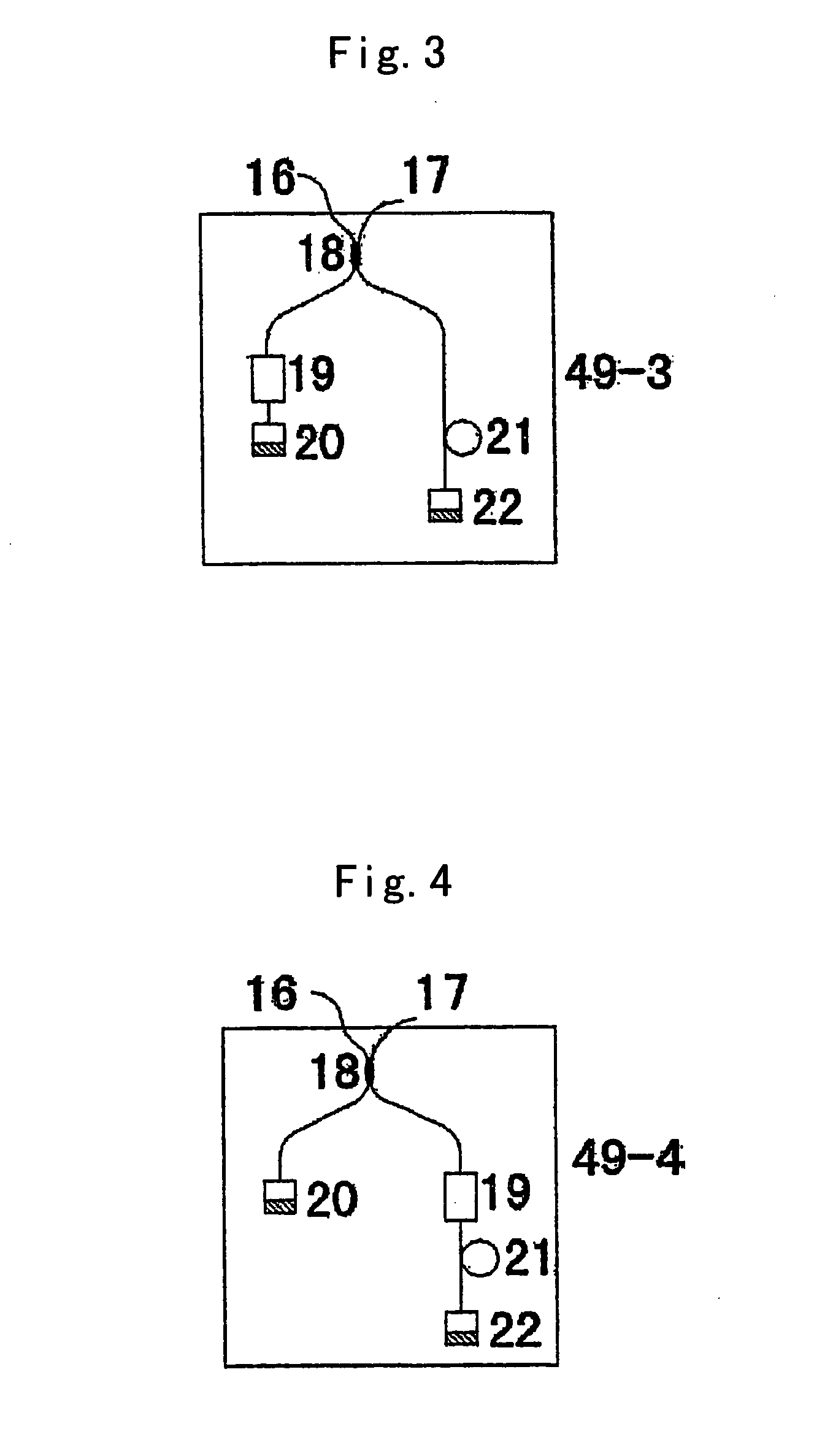
[0033] The third configuration of polarization-controlled encoder in quantum key distribution system is shown in FIG. 3. It includes one 2×2-3 dB beam splitter 18, two 90 degree Faraday mirrors 20 and 22, one phase modulator 19 and one delay line 21. The two ports 16 and 17 which are in the same side of 3 dB beam splitter 18 are input and output ports of polarization-controlled encoder respectively. One of the two ports which are in the other side of 3 dB beam splitter 18 connects with phase modulator 19 and 90 degree Faraday mirror 20 in turn. The other port connects with delay line 21 and 90 degree Faraday mirror 22 in turn. When the system works, an optical pulse is injected into port 16 of beam splitter 18 and divided into two pulses. One pulse pass through the delay line 21 and reflected back by 90 degree Faraday mirror 22. The other pulse pass through the modulator 19 and reflected back by 90 degree Faraday mirror 20. Then they are recombined by beam splitter 18 and output fro...


PUM


Abstract

The invention relates to a polarization-controlled encoding method, encoder and quantum key distribution system, which is characterized in that polarization maintaining light path or 90 degree rotation Faraday mirror are used inside the encoder to keep the polarization of the output pulses same, and that in the quantum key distribution system employing the polarization-controlled encoder the pulse emitted from transmitter is unidirectional-transmitted to receiver and then quantum key distribution is implemented using interference in the pulses according to the quantum key distribution protocol. The quantum key distribution system using the polarization-controlled encoder of the invention has the ability of avoiding the wiretapping to transmitter, receiver and quantum channel. Detection units each of which separates reversed photon from other photons are added at the out port of the transmitter and the in port of receiver, respectively, so that Trojan horse is prevented from entering and photons with phase modulated information are prevented from leaving the safe area in receiver. Unconditionally safe key distribution can be accomplished by using the quantum key distribution system of the invention.

Description

FIELD OF THE INVENTION [0001] This invention relates to the field of secure optical communication, and more particularly to an encoding method and device in quantum key distribution system. DESCRIPTION OF THE RELATED ART [0002] Early encoding scheme of quantum key distribution is based upon photon polarization. This scheme is fit for free-space communication instead of fiber communication. That's because the symmetry of normal fiber is not good and the interference in transmission path disturbs the polarization state, the photon polarization will be random changed during transmission in it. U.S. Pat. No. 5,307,410 disclosed a phase encoding scheme of quantum key distribution which bases on a pair of unbalanced Mach-Zehnder interferometers. Because the optical pulses pass through the different arms of the different interferometers in transmitter and receiver, the disturbance they suffered is not exactly identical to each other and can't be counteracted. The stability and anti-jamming...

Claims


Application Information

Patent Timeline
Patent Type & Authority Applications(United States)
IPC IPC(8): H04L9/08G02B6/27H04B10/18H04B10/20
CPCH04L9/0858
Inventor ZHENGFU, HANZHU, BINGMO, XIAOFANGUO, GUANGCAN
Owner ANHUI QASKY QUANTUM SCI & TECH CO LTD
Learn More