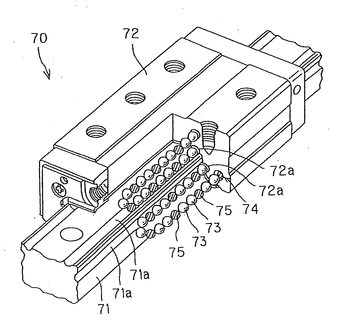
Rolling Guide Device
a technology of rolling guide and guiding rod, which is applied in the direction of rotary machine parts, mechanical equipment, gearing, etc., can solve the problems of insufficient adhesion performance or abrasion resistance of dlc film formed by pvd method or cvd method, limited use, and deterioration of dlc film in vacuum condition so as to achieve sufficient surface pressure, improve adhesion performance and abrasion resistan
- Summary
- Abstract
- Description
- Claims
- Application Information
AI Technical Summary
Benefits of technology
Problems solved by technology
Method used
Image

Examples
Embodiment Construction
[0054] Hereunder, preferred embodiments for embodying the present invention will be described with reference to the accompanying drawings. Further, it is to be noted that the following embodiments do not limit the inventions recited in the respective claims, and all the combinations of characteristic features described in the embodiments is not always essential for the solution of the present invention.
[0055] Furthermore, in the present embodiments, there are explained examples in which a thin film as a solid lubricant film is formed to a surface of a ball as a rolling member utilized for a rolling guide device by using a Closed magnetic Unbalanced Magnetron Spattering device (called CUMS device hereinlater) manufactured by a TEER Coatings Ltd. The reason why this device is utilized resides in that a plasma having high density can be obtained in comparison with a usual Unbalanced Magnetron Spattering method (UBMS™ method), and an ion current density five times higher than that of u...
PUM
| Property | Measurement | Unit |
|---|---|---|
| thickness | aaaaa | aaaaa |
| friction coefficient | aaaaa | aaaaa |
| friction coefficient | aaaaa | aaaaa |
Abstract
Description
Claims
Application Information
 - R&D
- Intellectual Property
- Life Sciences
- Materials
- Tech Scout
- Unparalleled Data Quality
- Higher Quality Content
- 60% Fewer Hallucinations
Browse by: Latest US Patents, China's latest patents, Technical Efficacy Thesaurus, Application Domain, Technology Topic, Popular Technical Reports.
© 2025 PatSnap. All rights reserved.Legal|Privacy policy|Modern Slavery Act Transparency Statement|Sitemap|About US| Contact US: help@patsnap.com