
Timepiece and Time Correction Method for a Timepiece

a timepiece and time correction technology, applied in the field of timepiece and time correction method for a timepiece, can solve the problems of significantly increasing power consumption, gps satellites predicted to fly overhead also changing, etc., and achieves the effect of increasing power consumption, quick capture of positioning information satellites, and correcting tim

Inactive Publication Date: 2008-02-07
SEIKO EPSON CORP
View PDF16 Cites 21 Cited by
  • Summary
  • Abstract
  • Description
  • Claims
  • Application Information

AI Technical Summary

Benefits of technology

[0013]However, if the user of the timepiece or other device having this GPS receiver mechanism moves to a different time zone, such as when travelling abroad, the GPS satellites predicted to fly overhead also change. The timepiece or GPS receiver does not know the time zone of its current location, however, and must therefore search for and capture the GPS satellites assuming that the current location is anywhere in the world. This significantly increases power consumption.
[0014]A timepiece and a time correction method for a timepiece according to the present invention can quickly capture positioning information satellites such as a GPS satellite and correct the time even if the current location changes greatly.
[0018]The GPS satellites or other positioning information satellites can therefore be quickly located and captured, and the problem of high power consumption resulting from capturing the positioning information satellites taking a long time is avoided. Highly precise time information can therefore be kept without high power consumption even if the location of the timekeeping device changes greatly.
[0020]Because the region information input unit is rendered in the time display unit of the timekeeping device and enables selecting region names, the timekeeping device user can simply select the region name of the destination, and the timekeeping device can then easily find the appropriate positioning information satellites and get the time correction information.
[0025]If the user of the timekeeping device accidentally operates the region information input unit but has not actually travelled to a different time zone, the timekeeping device will not attempt to capture the positioning information satellites based on the capturable satellite information for the region input as the destination, and accidental operation is thus prevented.

Problems solved by technology

However, if the user of the timepiece or other device having this GPS receiver mechanism moves to a different time zone, such as when travelling abroad, the GPS satellites predicted to fly overhead also change.
The timepiece or GPS receiver does not know the time zone of its current location, however, and must therefore search for and capture the GPS satellites assuming that the current location is anywhere in the world.
This significantly increases power consumption.

Method used


Image

  • Timepiece and Time Correction Method for a Timepiece
  • Timepiece and Time Correction Method for a Timepiece
  • Timepiece and Time Correction Method for a Timepiece

Examples


embodiment 1

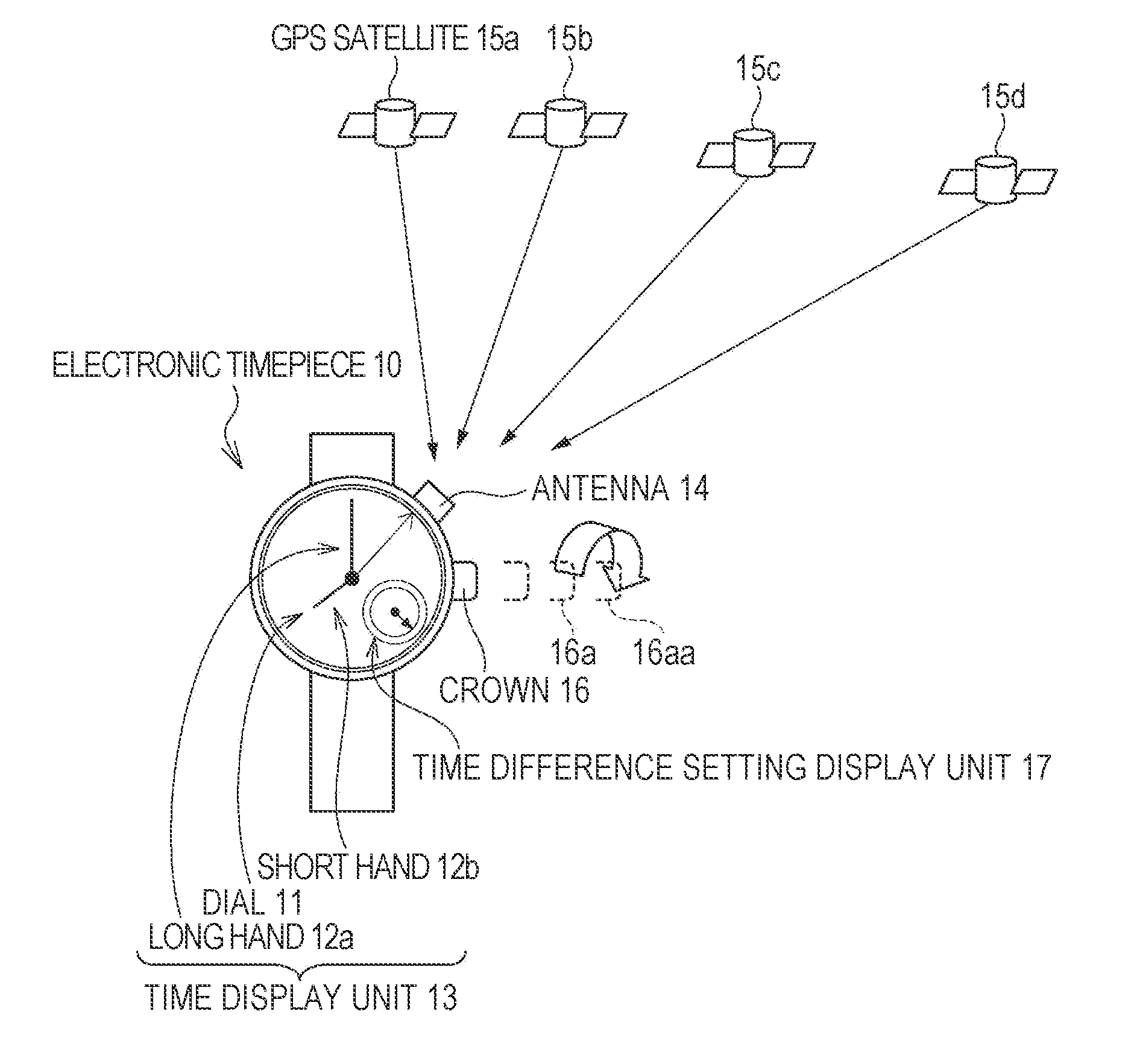
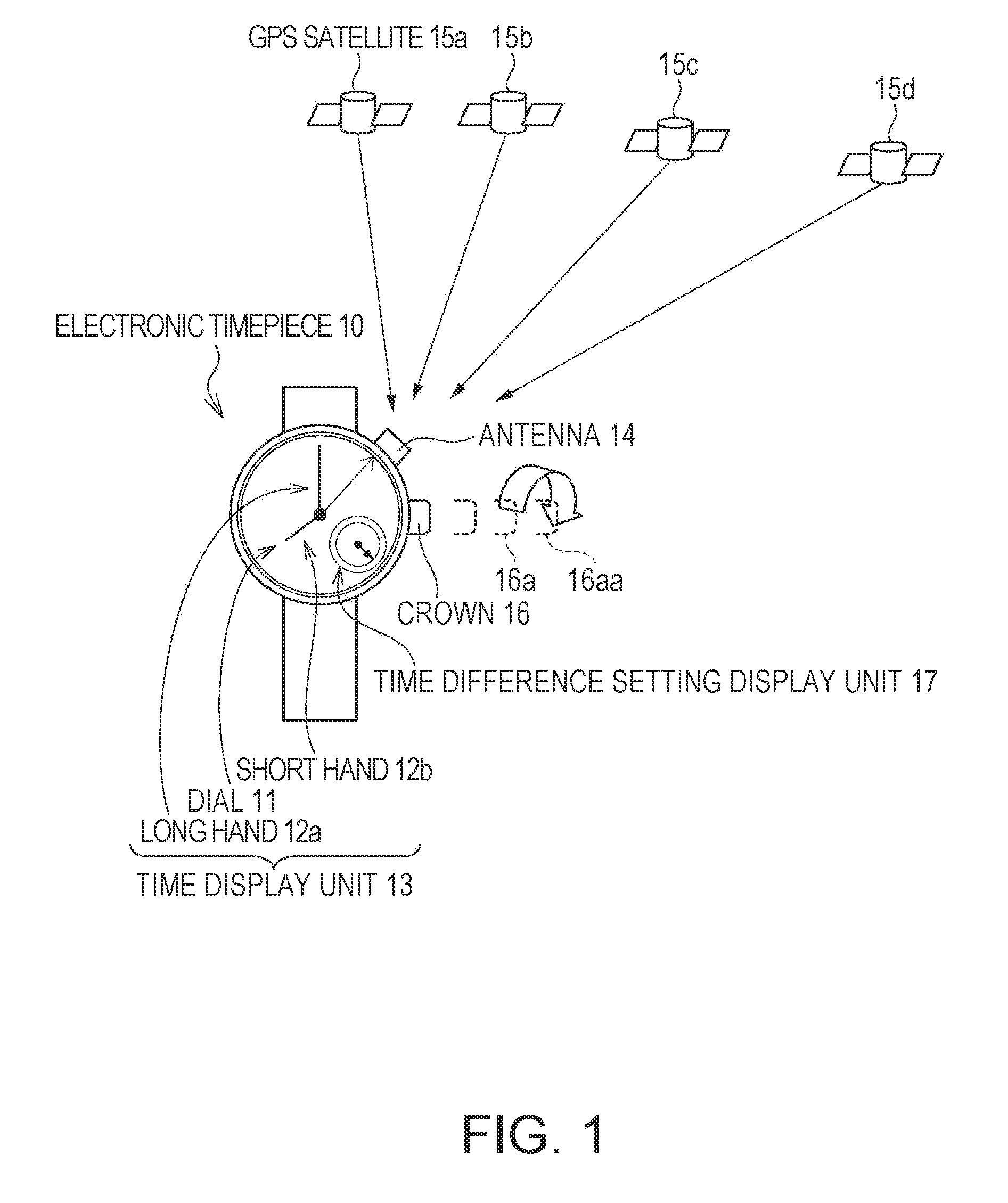
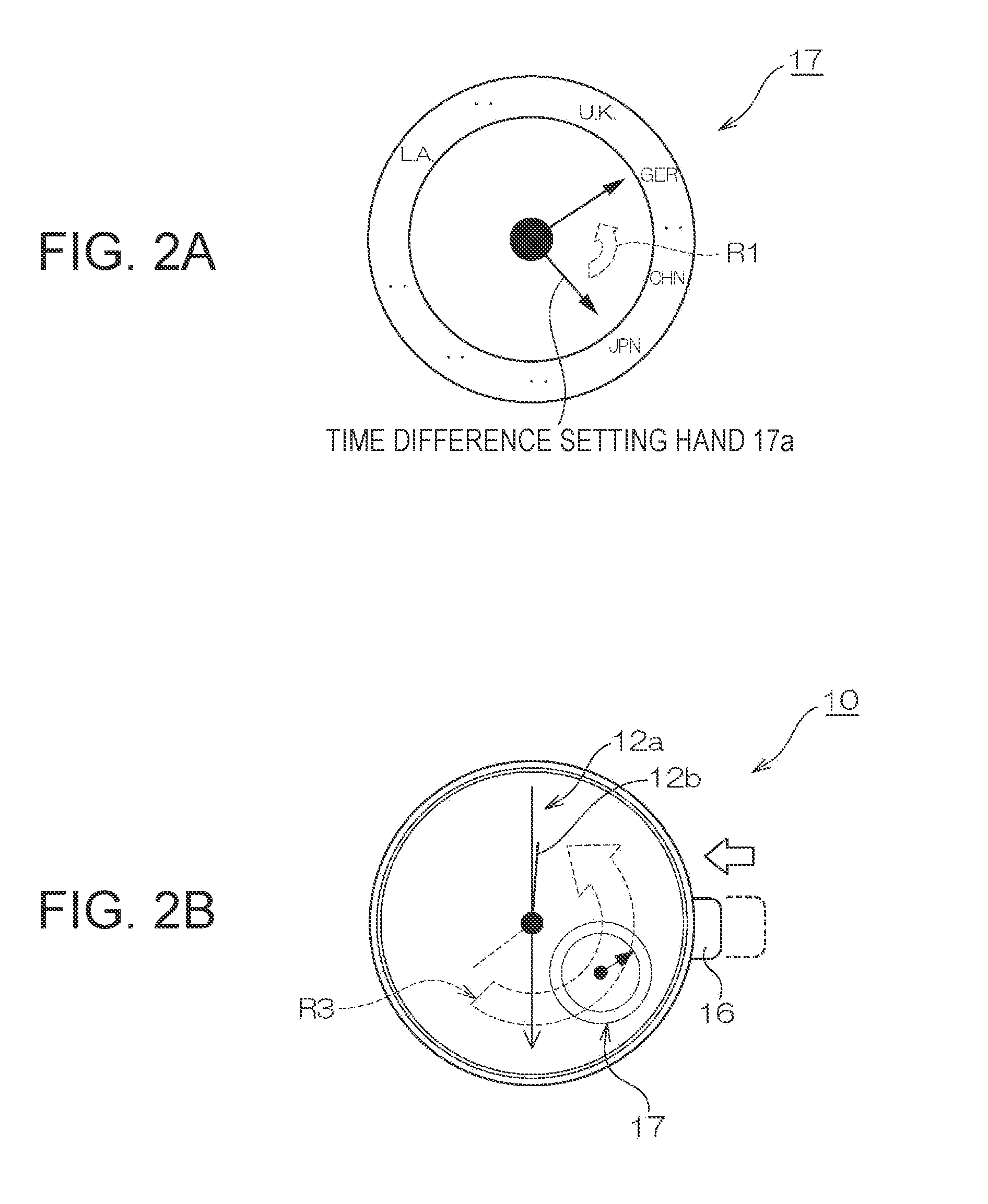
[0039]FIG. 1 is a schematic diagram of an electronic timepiece 10 as a first embodiment of a timepiece according to the present invention. As shown in FIG. 1 a time display unit 13 having a dial 11 and hands such as a long hand 12a and a short hand 12b for displaying the time is rendered on the front of the electronic timepiece 10. The electronic timepiece 10 also has a crown 16 for adjusting the hands and operating the timepiece.

[0040]An antenna 14 for receiving satellite signals from the GPS satellites 15a to 15d is rendered on the side of the electronic timepiece 10 as shown in FIG. 1.

[0041]These GPS satellites 15a are examples of positioning information satellites orbiting the Earth.

[0042]More specifically, the electronic timepiece 10 according to this embodiment of the invention determines its own position by receiving signals from GPS satellites 15a, and uses data from the atomic clocks of the GPS satellites 15a to acquire precise time information as described below.

[0043]The ...

embodiment 2

[0117]FIG. 9 is a schematic diagram of an electronic timepiece 100 according to a second embodiment of the invention. The electronic timepiece 100 according to this embodiment of the invention is substantially the same as the electronic timepiece 10 of the first embodiment, and is described below with reference to the differences.

[0118]This embodiment does not have the time difference setting display unit 17 shown in FIG. 2. To set the time difference in this embodiment, therefore, the user pulls the crown 160 out three stops as shown in FIG. 9A and then turns the crown 160 to move the short hand 120a.

[0119]If the electronic timepiece 100 user travels from Japan to China, for example, the short hand 120a is moved in the direction of arrow R2 to set the time back one hour as shown in FIG. 9B. This adds 8 hours to the UTC in the nationally (regionally) capturable GPS satellite data 41a shown in FIG. 7, and sets the time difference to the time difference in China.

[0120]When the crown ...


PUM


Abstract

A timekeeping device having a reception unit that captures positioning information satellites orbiting the Earth and receives satellite signals from the captured positioning information satellites; a time correction information generating unit that generates time correction information based on the satellite signals received by the reception unit; a display information correction unit that corrects displayed time information based on the time correction information; a capturable satellite information storage unit that stores capturable satellite information relating to the positioning information satellites that can be captured in the region where the reception unit is located; and a region information input unit for inputting the region information for the location of the reception unit. The reception unit captures the positioning information satellites based on the region information input through the region information input unit and the capturable satellite information.

Description

CROSS-REFERENCE TO RELATED APPLICATIONS[0001]Japanese Patent application No.(s) 2006-213482 is hereby incorporated by reference in its entirety.BACKGROUND[0002]1. Field of Invention[0003]The present invention relates to a timepiece that sets the time based on a signal received from a GPS satellite, for example, and to a time correction method for the timepiece.[0004]2. Description of the Related Art[0005]The Global Position System (GPS), which is a system enabling a receiving device to determine its own position, uses satellites (GPS satellites) that each orbit the Earth on a specific path. Each GPS satellite has an on-board atomic clock and keeps time with extremely high precision.[0006]Japanese Patent No. 3512068 (JP2001-59864) (paragraph [0001]), for example, teaches a method of using data from the atomic clock of a GPS satellite to correct the time kept by a timepiece with high precision.[0007]However, in order to get atomic clock data from a GPS satellite, the GPS receiver must...

Claims


Application Information

Patent Timeline
Patent Type & Authority Applications(United States)
IPC IPC(8): G04B47/06G01S1/00G01S19/14G01S19/28G01S19/34G04G5/00G04R20/00G04R20/02
CPCG01S19/14G04R40/02G04R20/02G04G5/002
Inventor MATSUZAKI, JUNHONDA, KATSUYUKIFUJISAWA, TERUHIKOURANO, OSAMU
Owner SEIKO EPSON CORP
Learn More