
RF-activated tag and locator

a locator and activation tag technology, applied in direction finders, instruments, signalling systems, etc., can solve the problems of extremely long battery life and no rf activation tag device produced, and achieve the effects of reducing false triggering, low quiescent power consumption, and reducing false triggering

Inactive Publication Date: 2008-02-07
FRIES ROBERT GORDON
View PDF34 Cites 28 Cited by
  • Summary
  • Abstract
  • Description
  • Claims
  • Application Information

AI Technical Summary

Benefits of technology

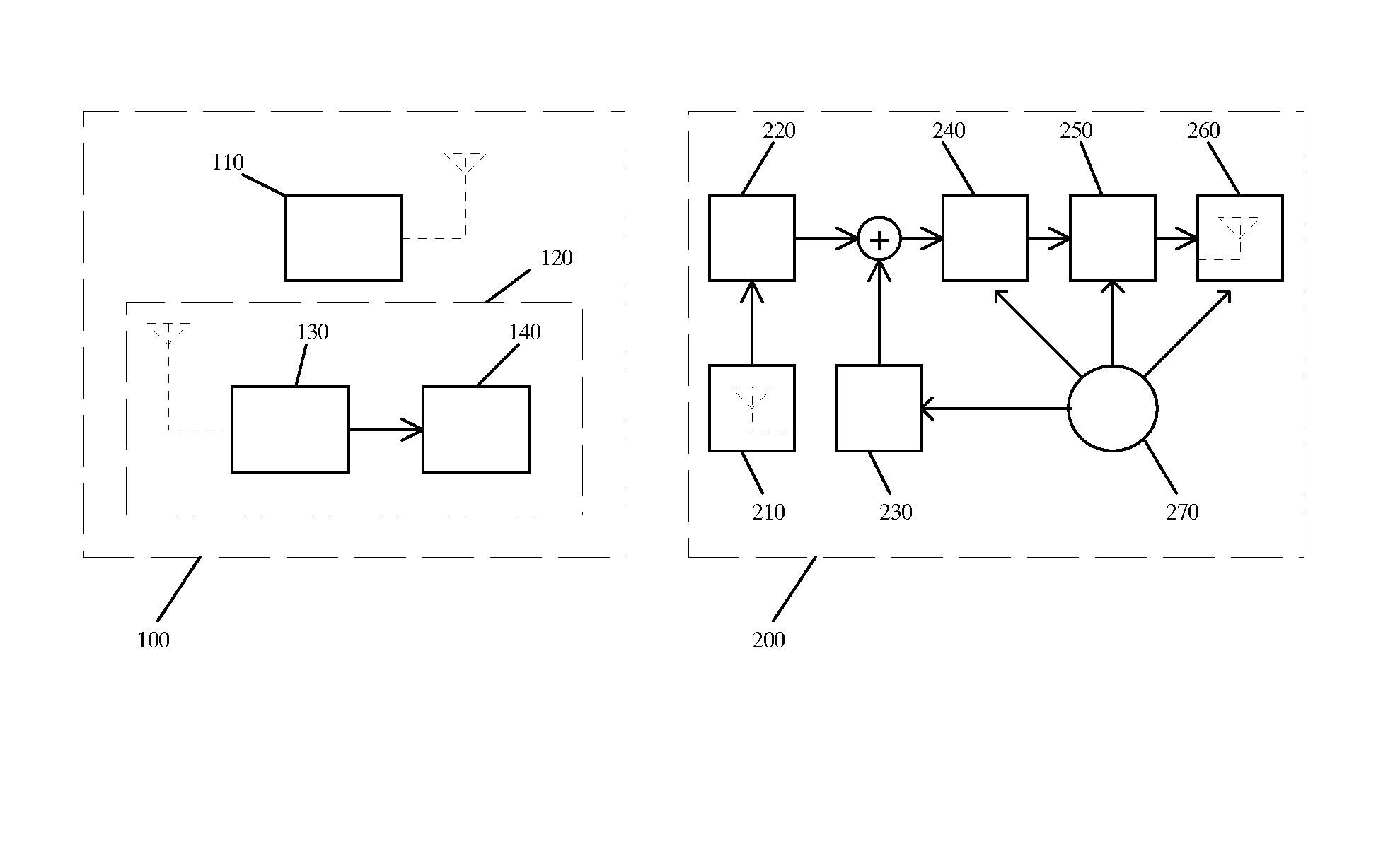
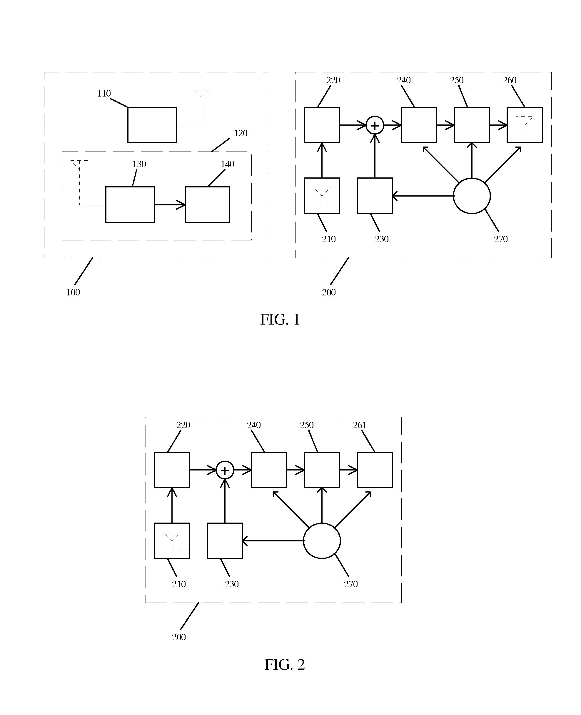
[0011] The present invention's tag device is activated in response to an activation signal produced by the companion locator device. The activation signal could be modulated, unmodulated, single frequency, spread-spectrum and / or multiple radio frequencies. When the locator device is within range of a tag device, the tag's passive RF energy detector circuit(s) converts the ambient RF energy from the locator into one or more small output signal(s). The signal(s) is / are then buffered. The buffered signal(s) in turn activate(s) a response mechanism. If multiple separate-frequency energy detectors are used, all frequencies would need to be transmitted in order to activate the response mechanism, reducing false triggering. A single transmitter could hop between the frequencies, or multiple individual transmitters could be used. This approach, specifically the use of a passive RF detector rather than an active receiver, enables the construction of tag devices with extremely low quiescent power consumption. Tags can also be designed with moderate (rather than maximum) sensitivity in order to reduce false triggering, and this approach usually also yields lower quiescent current consumption.
[0012] To date, no RF-activated tag device has been produced that is compact enough to permit locating items such as eyeglasses while also providing extremely long battery life. One embodiment of the present invention yields a tag device which measures approximately 1.2″ in length and 0.190″ in width, including the battery. This is small enough to attach to a leg of a pair of eyeglasses without causing discomfort to the user or affecting the cosmetic appearance of the glasses, as the tag can be placed on the rear portion of the eyeglasses leg which is normally concealed behind the ear. This same form factor could be used with many other items, including keychains, wallets, sunglasses, luggage tags, coffee cups and cell phones, to name only a few.
[0014] When attached to eyeglasses with a metal support structure in the frame, the metal, though electrically isolated from the tag, usually acts as a supplementary antenna, increasing the activation sensitivity of the tag and potentially increasing the tag's RF response signal.
[0015] One tag embodiment typically consumes less than 100 nA of quiescent current. The SR416 (or type 377) watch battery is 4.8 mm×1.65 mm, roughly matching the width and height of the aforementioned tag's circuit board, and has a capacity rating of 8 mA-hours. Using this battery, the shelf life of this tag will be about 3 years if never activated, or would be about 2 years with 10 activations per month of 10 seconds each, or would be 2.5 years with 4 activations per month of 10 seconds each, assuming 4 mA activated current consumption. This permits the tag to be permanently sealed against environmental contaminants, as the tag can use a non-replaceable power source while still providing long operating life. Such sealing could be by means of an enclosure, a protective coating or other means. Further circuitry refinements may reduce the quiescent current even more and correspondingly increase the operating life. Other ways of increasing tag useful life could employ, for example, placing two such batteries in parallel, or using one or more larger-capacity batteries such as type 348 (which is also 4.8 mm diameter but thicker at 2.15 mm, and has an energy capacity of 12 mAh).

Problems solved by technology

To date, no RF-activated tag device has been produced that is compact enough to permit locating items such as eyeglasses while also providing extremely long battery life.

Method used


Image

  • RF-activated tag and locator
  • RF-activated tag and locator
  • RF-activated tag and locator

Examples


Embodiment Construction

[0028] A self-contained tag device could be sealed from the environment by an enclosure, a protective coating such as an epoxy dip, or other protective means, and would generally employ a power source. A tag device that is incorporated within or integrated into another object may use the power source of the object, if available, and the object's enclosure would provide protection for the tag circuitry.

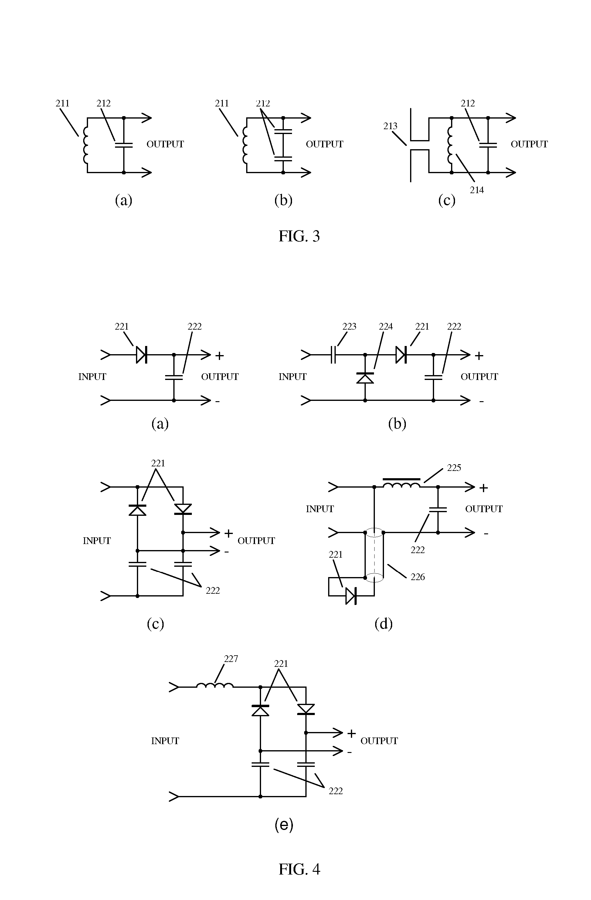
[0029]FIG. 1 shows one embodiment of a locator device (100) and a tag (200), where the tag (200) provides an RF response. The tag device (200) provides a tuned antenna (210) designed to resonate at a frequency generated by the transmitter (110) of the locator device (100). The signal transmitted by the locator's transmitter (110) would ideally be in an unlicensed frequency band such as 315 MHz, 433 MHz, 462 MHz, or 902-918 MHz. The tuned antenna (210) is coupled to a detector circuit (220) to provide an output signal. The detector's output is optionally summed with the output of an op...


PUM


Abstract

An object locating system employing tags and a handheld locator. A unique low power tag circuit enables highly compact form factor and extremely long operating life even from the smallest available batteries. The tag employs an efficient passive RF energy detector circuit rather than an active receiver, as well as a novel low-power temperature-compensated biasing circuit to provide uniform sensitivity over a broad temperature range. The locator device transmits a tag activation signal, receives tag RF responses, and reports presence and optionally proximity changes to the user. An alternate tag design directly conveys proximity changes. The locator may also incorporate tag functionality to aid in finding a misplaced locator.

Description

[0001] This application is a continuation of U.S. patent application Ser. No. 11 / 756,617, filed May 31, 2007, and claims the benefit of the prior Provisional application 60 / 803,536 filed on May 31, 2006.FIELD OF THE INVENTION [0002] The present invention relates to the field of object locating systems in general, and to RF-based locator devices specifically. BACKGROUND OF THE INVENTION [0003] There are many potential uses for a system which can indicate nearness to, and / or being in the presence of, a ‘tag’ which is attached to an object or a person. One use would be to identify an item uniquely out of a collection of items. Another use would be to locate lost items. There are a variety of item locating and identifying systems on the market. Tags which are activated by a radio frequency (RF) signal generally focus on maximizing the tag activation distance, along with employing an audible or visual response. Visual response mechanisms are obviously limited in usefulness if the object ...

Claims


Application Information

Patent Timeline
IPC IPC(8): G08B1/08
CPCG01S3/38G06K19/0723G06K19/0701
Inventor FRIES, ROBERT GORDON
Owner FRIES ROBERT GORDON
Learn More