Heat exchanger tube with integral restricting and turbulating structure

Inactive Publication Date: 2008-02-07
BECKETT GAS
View PDF48 Cites 48 Cited by
  • Summary
  • Abstract
  • Description
  • Claims
  • Application Information

AI Technical Summary

Benefits of technology

[0007] A more particular object of the present invention is to provide a heat exchanger tube with an integral restricting and turbulating structure which allows for drainage of liquid from the tube even when located in a horizontal section of the tube. Another more particular object of the invention is to provide a heat exchanger tube which can have integral restricting and turbulating structures between bends in a serpentine shaped heat exchanger.
[0009] In order to maximize the efficient transfer of heat from the hot gases within the tube to the air or other fluid media outside the tube, a restricting and turbulating structure is used to slow the rate of travel of the hot gases through the tube. The restricting and turbulating structure of the present invention comprises dimples formed in the sides of the heat exchanger tube. The heat exchanger tube with dimples pressed in it maintains a cross sectional profile that does not extend beyond that of the undimpled tube, preventing difficulties associated with flattening techniques. The dimples are comprised of pairs of indentations opposite one another along the tube. The indentations may extend into the tube to such depth as is necessary to provide the required restriction. These indentations are located directly opposite from each other, constituting a dimple which significantly reduces the cross sectional area of the tube. This dimple form provides a structure approximating a pair of converging, diverging nozzles. This two nozzle dimple structure provides improved turbulence. In applications requiring condensate drainage, the dimples are preferably located only along the sides of the tube, with the axis of the dimple being perpendicular to the vertical centerline of the tube as it is oriented in use. This provides a non-deformed tube along the bottom of the horizontal sections, which provides liquid condensate and an unobstructed flow path. In short, the dimples do not obstruct the flow of liquid out of the tube. Exact dimple geometry and location may be adjusted to maximize efficient turbulence of the hot gases, depending on the final shape and orientation of the tube.
[0013] The present invention provides a heat exchanger tube suitable for use in commercial and light commercial heating and air conditioning units as well as other commercial and residential products. The present invention incorporates an effective restricting and turbulating structure which does not require additional parts such as baffles. The present invention provides a heat exchanger tube having a cross section which does not extend outside the cross section of the heat exchanger tube without dimples. In addition, the present invention does not interfere with drainage of condensation, even when the heat exchanger tube is bent into a serpentine shape, thereby reducing the possibility of corrosion. In applications where condensate drainage is not an issue, dimples can be located rotationally at any desired angle from each other to provide additional mixing and turbulence. The present invention also provides a superior turbulating method by providing adjacent converging, diverging nozzles in a tubular heat exchanger regardless of shape or tube orientation. The turbulating characteristics of the present invention can be controlled by controlling an aperture size of the nozzles or the depth and longitudinal spacing of the dimples.

Problems solved by technology

One problem associated with baffles in tubes is noise caused by expansion or contraction of baffles or vibrations generated by the mechanical coupling to components such as blowers or fans.
Another difficulty related to the use of baffles is that the heat exchanger tube cannot be bent with a baffle already inserted so that baffles must be inserted after bending, limiting the typical location of baffles to straight sections of the heat exchanger tube which are accessible after bending.
In addition, the use of separate baffles increases the cost and difficulty of assembling the heat exchanger.
A problem with the use of flattened sections is that this technique extends the cross section of the tube beyond that of the tube without deformations, creating low spots in horizontal sections.
While deformation of the heat exchanger tube can replace the use of baffles in some applications, the deformation technique has had less than satisfactory results when applied in commercial and light commercial heating and air conditioning units.
Therefore, during use for air conditioning the cool air passing over the heat exchanger lowers the tube temperature below the dew point of air inside the tube, resulting in condensation inside the tube.
Current configurations of tube deformation experience problems in draining this condensation from the tube due to low spots in the horizontal sections of the tube.
The low spots, which are caused by restricting deformations prevent the flow of liquid, allowing condensate to puddle and increase the likelihood of corroding the tube.

Method used


Image

  • Heat exchanger tube with integral restricting and turbulating structure
  • Heat exchanger tube with integral restricting and turbulating structure
  • Heat exchanger tube with integral restricting and turbulating structure

Examples


Embodiment Construction

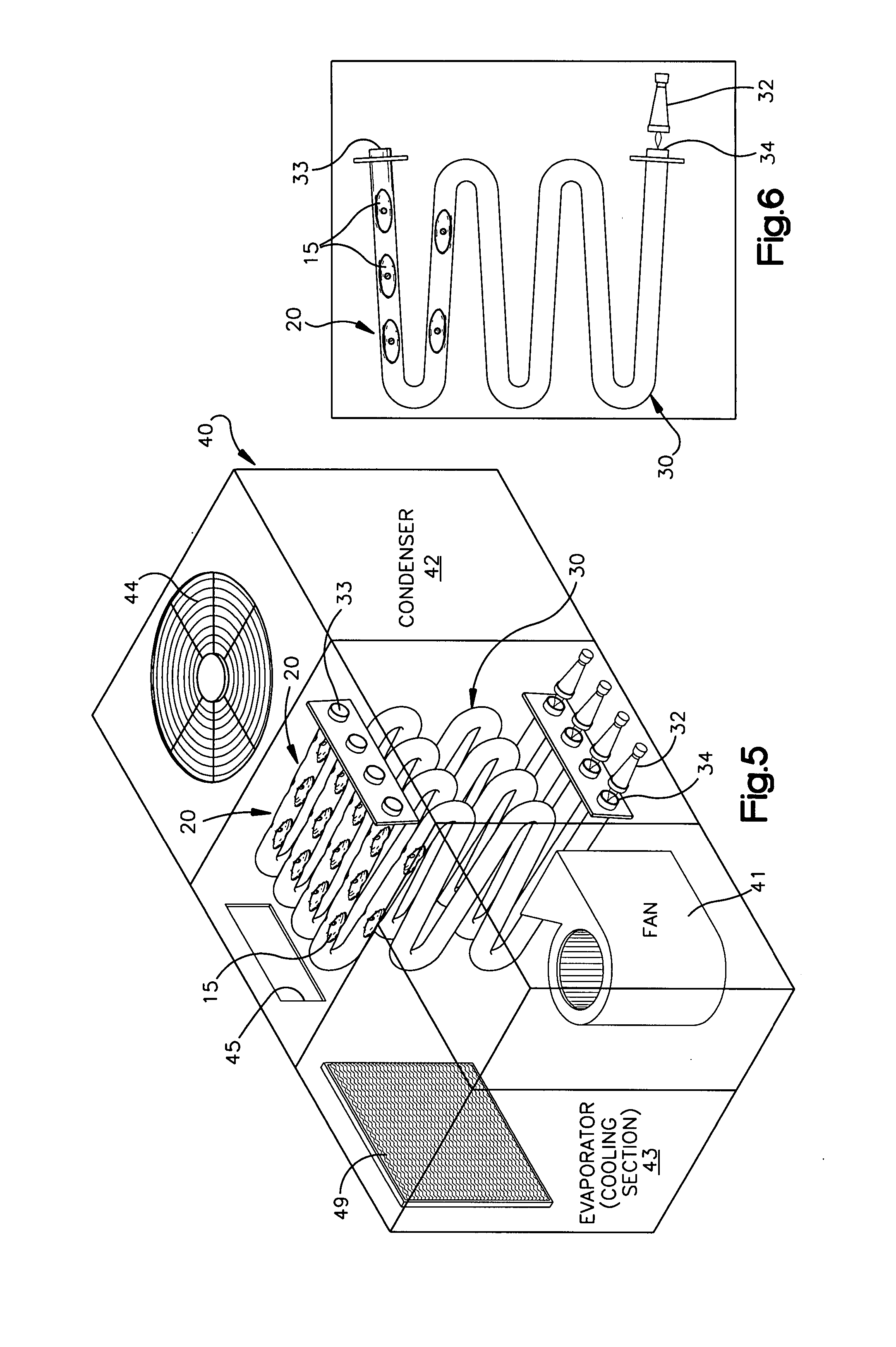
[0031]FIGS. 1-9 illustrate the construction of heat exchanger tubes 10, 30, 10′ constructed in accordance with preferred embodiments of the invention. The heat exchanger tube of the present invention may be used in many heating applications including, but not limited to, furnaces, water heaters, unit heaters and commercial ovens.

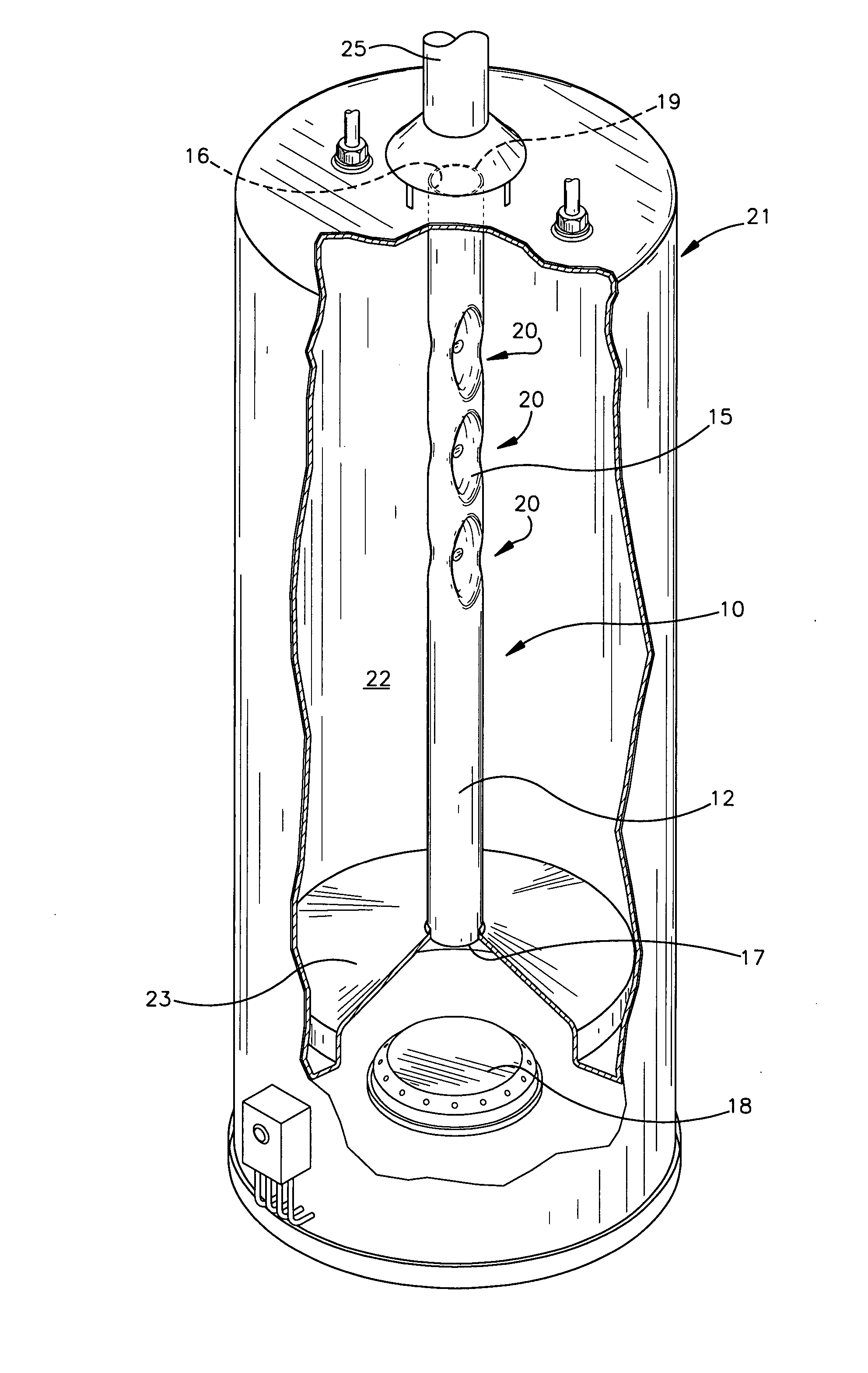
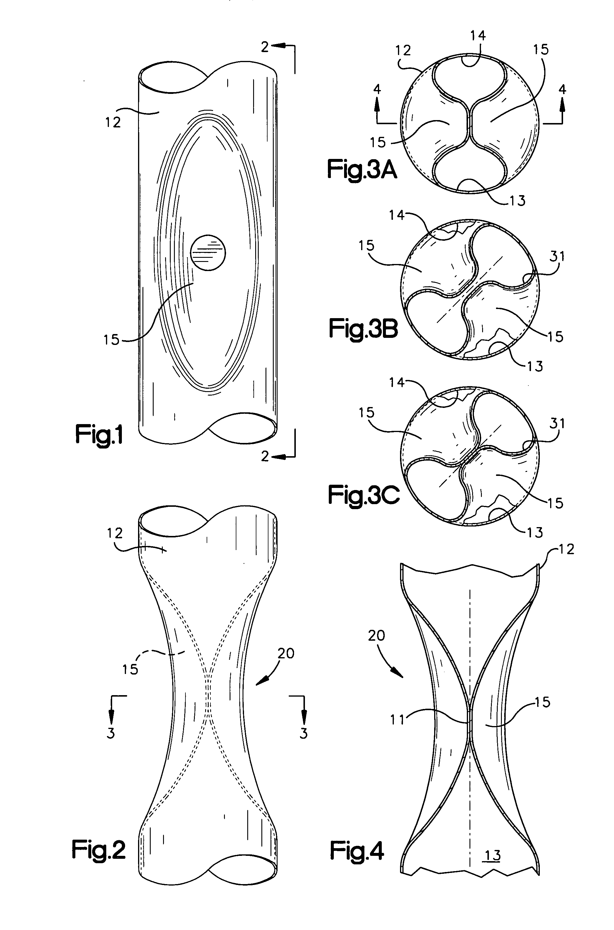
[0032] To facilitate the explanation, the tube construction shown in FIGS. 1-4 will be described first in connection with its use as a flue tube in a water heater (shown in FIG. 7). Referring also to FIG. 7, a gas heated residential water heater 21 is shown having a flue tube 10 of the present invention extending upwardly through a water heating chamber 22. The flue tube 10 consists primarily of a metal tube 12. The metal tube 12 has an interior surface 16, an inlet end 17, and an outlet end 19. At least one parabolic shaped indentation 15 is pressed into the metal tube 12. In the preferred embodiment, the indentations 15 are pressed into the metal tube 12 ...


PUM


Abstract

A heat exchanger tube having an integral restricting and turbulating structure consisting of dimples formed by confronting indentations pressed into the sides of the heat exchanger tube. The dimples are comprised of indentations disposed in pairs which extend into the tube to such a depth as is necessary to significantly reduce the cross sectional area of the heat exchanger tube. The dimples of a pair are staggered or offset, longitudinally with respect to each other such that a restrictive passage is defined between each pair of offset dimples. The turbulence characteristics of the tube can be controlled by varying the depth to which the dimples project into the tube and the longitudinal spacing between the dimples that comprise the pair. Adjacent pairs of dimples may be rotated 90° with respect to each other or alternately can be arranged in a helix pattern.

Description

RELATED APPLICATION [0001] This is a continuation-in-part application of U.S. Ser. No. 10 / 721,682, filed on Nov. 25, 2003.TECHNICAL FIELD [0002] The invention relates to appliances which employ tubular elements for the purpose of conveying flue products and transferring heat to fluid media adjacent to the exterior of the tube. Product groups include, but are not limited to, furnaces, water heaters, unit heaters and commercial ovens. BACKGROUND [0003] A typical method of making heat exchangers for a variety of gas and oil fired industrial or residential products is to bend a metal tube into a serpentine shape thereby providing multiple passes. Gases heated by a burner at one end of the heat exchanger travel through the tube interior and exit the other end of the heat exchanger. While the hot flue gases are within the tube, heat is conducted through the metal walls of the tube and transferred to the air or other fluid media surrounding the tube thereby raising its temperature. In orde...

Claims


Application Information

Patent Timeline
IPC IPC(8): F28F1/06
CPCF24H3/087F24H9/0026F28D21/0003F28F1/06F28F2001/027F28F1/426F28F13/08F28F13/12F28F1/42
Inventor O'DONNELL, MICHAEL J.SLABY, TERRANCE C.
Owner BECKETT GAS
Why Eureka
Try Eureka