
Method and Apparatus for Distributing USB Hub Functions across a Network

a technology of usb hub and network, applied in the direction of instruments, electric digital data processing, data switching by path configuration, etc., can solve the problems of limiting the extent to which the range of usb can be extended, clumsy, and expensive multi-hub solutions, and achieve the effect of cost-effectiveness

Active Publication Date: 2008-01-31
ICRON TECH
View PDF23 Cites 71 Cited by
  • Summary
  • Abstract
  • Description
  • Claims
  • Application Information

AI Technical Summary

Benefits of technology

[0019]It is a further object of the present invention that no hardware or software changes need be made to the existing host computers, hubs and devices supported by the system and operating under the USB protocol. The invention, thereby, may be incorporated into networks composed of both conventional delay and extended delay devices.
[0022]It is a further object of the present invention that the apparatus be very cost effective, consistent with the broadest population of devices targeted by the USB industry.

Problems solved by technology

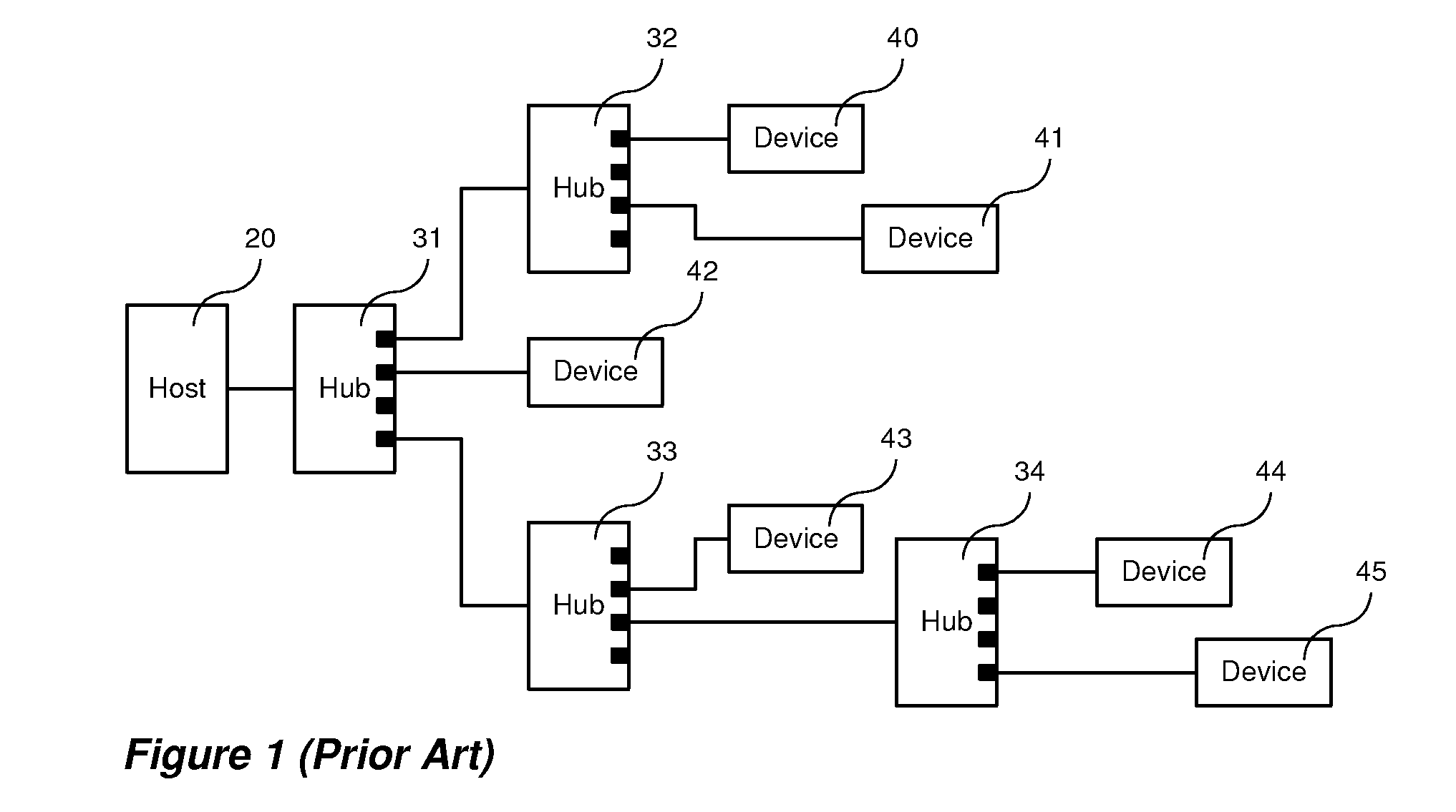
However, this multiple hub solution is both expensive and clumsy.
The major factor that limits the extent to which the range of USB can be extended is transmission delay.
While the approach described in U.S. Pat. No. 6,381,666 made it possible to operate USB peripheral devices over an extended distance and in the presence of long transmission delays, it did not describe a configuration in which a plurality of USB peripheral devices are widely separated from each other.
The USB driver software resident in the host computer that contains the USB host controller is aware of the connection topology of USB hubs and USB peripheral devices and will fail to operate if said topology is not maintained.

Method used


Image

  • Method and Apparatus for Distributing USB Hub Functions across a Network
  • Method and Apparatus for Distributing USB Hub Functions across a Network
  • Method and Apparatus for Distributing USB Hub Functions across a Network

Examples


Embodiment Construction

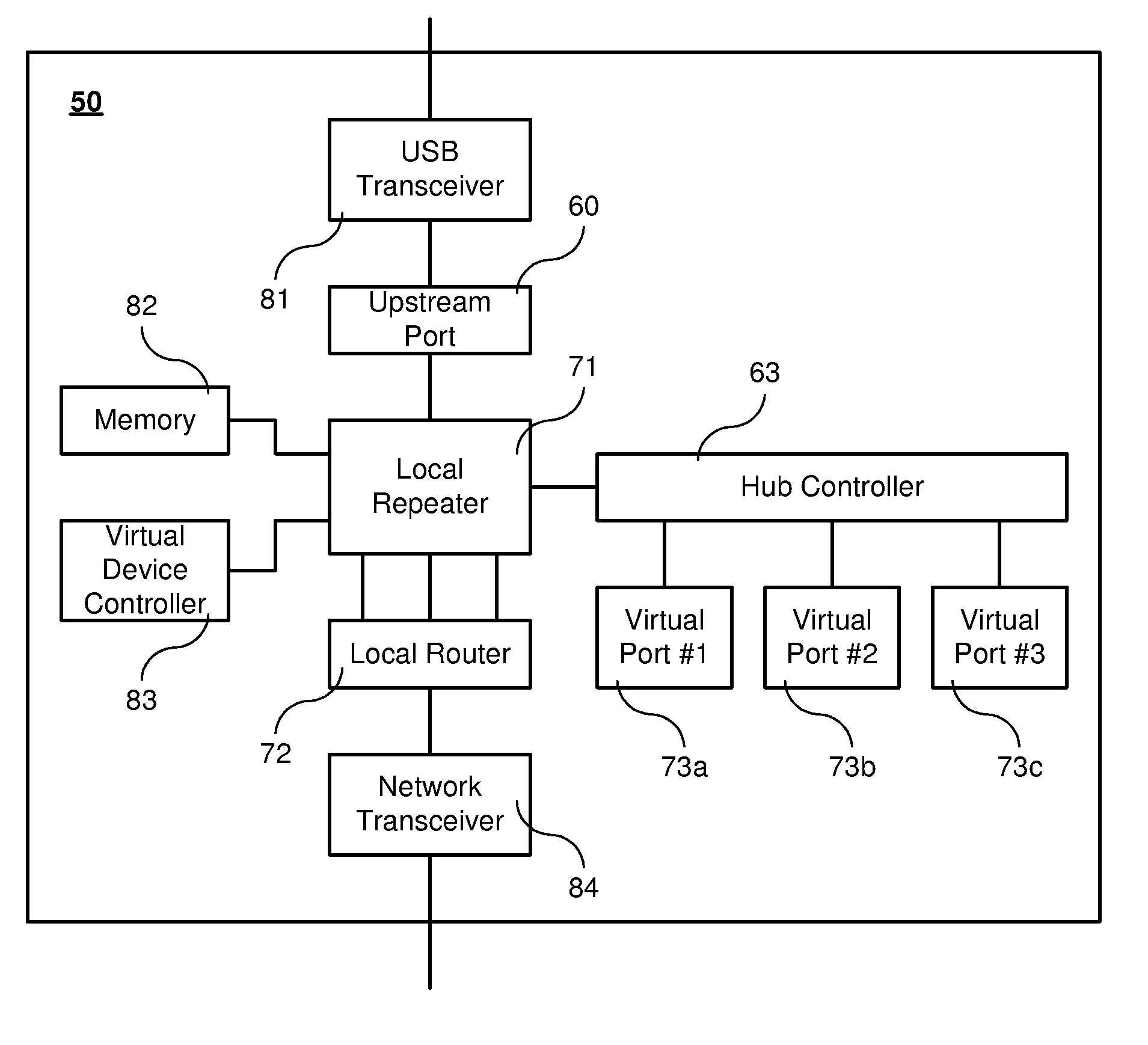
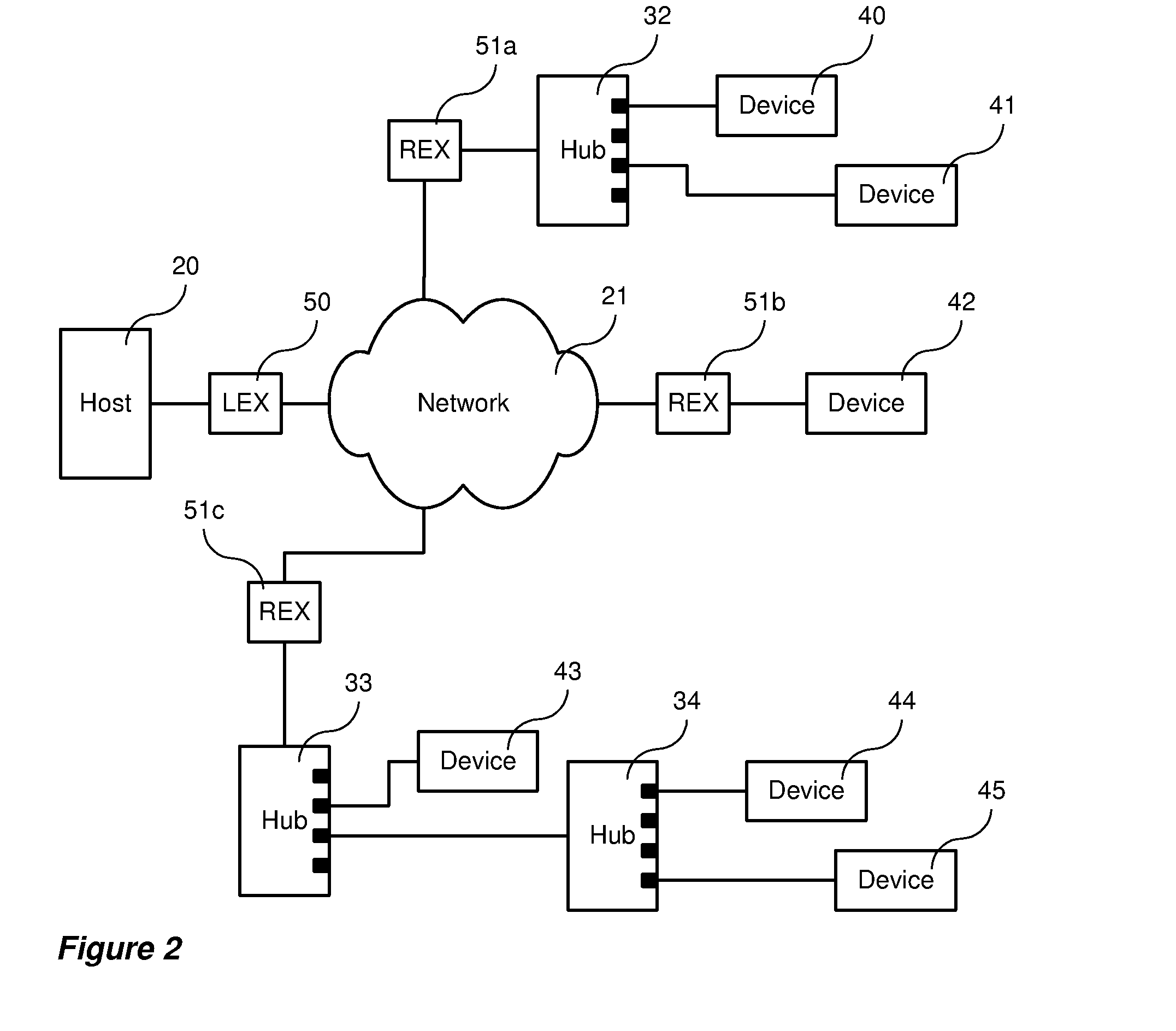
[0147]In a preferred embodiment, the host computer and the USB peripheral device can be any standard unit or device that supports the USB Specification. Preferably, no modifications to either the hardware or the software of said host computer are required.

[0148]The local extender is preferably a self-contained unit that connects to said host computer through a standard USB cable.

[0149]The remote extender is preferably a self-contained unit that connects to said plurality of USB peripheral devices through a plurality of standard USB cables.

[0150]The data communications network is not limited to any particular transmission media or protocol, but can, in operation, introduce a round-trip transmission delay between said host computer and said plurality of USB peripheral devices in excess of 1 microsecond. It is a necessary attribute of said data communications network that it provide a communications path between at least one local extender unit and at least one remote extender unit. It...


PUM


Abstract

A method and related apparatuses for data transmission between a host computer and one or a plurality of USB compliant peripheral devices over a data communications network is provided which operates in the presence of transmission delays greater than that normally allowed in the USB specification. The host computer is connected to a local extender device which, in turn, is connected to one or a plurality of remote extender devices through the data communications network. The remote extender devices are, in turn, connected to a plurality of conventional USB peripheral devices. Data between the host computer and peripheral devices is stored and processed in the local and remote extender devices in order to allow the host computer and the USB peripheral devices to operate with greater than normally allowed time delays. In particular, the invention is of most utility when the round-trip transmission delay between the host computer and the USB peripheral device exceeds 1 microsecond.

Description

FIELD OF THE INVENTION[0001]This invention relates to methods and apparatus for transmitting signals between computers and devices using Universal Serial Bus (USB) ports, and, in particular, to a method for operating a plurality of USB peripheral devices distributed across a data communications network.DESCRIPTION OF THE PRIOR ART[0002]Universal Serial Bus (USB) is a technology designed to permit a wide range of peripherals to be attached to personal computers by the average user. The technology supports all of the common peripheral devices such as keyboards, mice, speakers, joysticks, cameras, flash drives, hard drives, DVD drives and many others, and its use in current computers is common.[0003]USB was created by an alliance of seven of the largest companies in the computer and communication markets. Those companies were Intel, Compaq, Microsoft, NorTel, NEC, Digital and IBM. The specifications defining USB (e.g. Intel et al., Universal Serial Bus Specification, Revision 1.0, Janu...

Claims


Application Information

Patent Timeline
IPC IPC(8): G06F13/20
CPCG06F13/4045
Inventor MCLEOD, JOHN ALEXANDER
Owner ICRON TECH
Learn More