Methods and materials for stabilizing analyte sensors

a technology of analyte sensors and materials, applied in medical preparations, diagnostics, medical science, etc., can solve the problems of affecting sensor performance, introducing noise, and deposition of protein or fouling on the surface of materials or devices, so as to enhance sensor performance and stability, and reduce noise

Active Publication Date: 2008-01-31
MEDTRONIC MIMIMED INC
View PDF94 Cites 16 Cited by
  • Summary
  • Abstract
  • Description
  • Claims
  • Application Information

AI Technical Summary

Benefits of technology

[0006]The invention disclosed herein has a number of embodiments. Typical embodiments include a sensor system designed to reduce noise and / or enhance sensor performance and stability, typically by creating a buffer zone (i.e. a protected zone where alterations in chemical reaction conditions are inhibited and / or minimized) at the 3-D interface where the analyte reacts with the sensor. One illustrative embodiment is a sensor system comprising a sensor having a chemically reactive surface that reacts with an analyte to be sensed; and a cannula comprising a substantially cylindrical housing that surrounds the sensor; at least one aperture disposed in the housing that allows the analyte to diffuse therethrough so as to contact the chemically reactive surface; and an end that extends beyond an end of the sensor.
[0007]Such sensor systems can be used in a variety of methods designed to enhance sensor function, for example long term sensor performance. Another embodiment of the invention is a method of stabilizing an environment for a chemical reaction between an in vivo analyte and an enzyme that reacts with the analyte, the method comprising performing the chemical reaction using an implanted sensor system comprising a sensor having a chemically reactive surface comprising the enzyme; and a cannula comprising a substantially cylindrical housing that encircles the sensor; at least one aperture disposed in the housing that allows the analyte to diffuse therethrough so as to contact the chemically reactive surface; and an end that extends beyond an end of the sensor, wherein the aperture and the chemically reactive surface of the implanted sensor system form a stabilized chemical reaction environment that is further stabilized by the end of the cannula that extends beyond an end of the sensor, so that the environment for the chemical reaction between the in vivo analyte and the enzyme that reacts with the analyte is stabilized.
[0008]The methods that utilize the sensor systems of the invention are useful in a variety of contexts. For example, the methods can be used so that the environment of the chemical reaction is stabilized so as to inhibit fluctuations in the ratio between the signal generated by the analyte and signal noise not generated by the analyte. Alternatively, the methods can be used so that the environment of the chemical reaction is stabilized so as to inhibit fluctuations in the ratio between the signal generated by the analyte and signal noise not generated by the analyte that results from movement of the sensor at the site of implantation. Alternatively, the methods can be used so that the environment of the chemical reaction is stabilized so as to inhibit fluctuations in the ratio between the signal generated by the analyte and signal noise not generated by the analyte that results from the accumulation of in vivo materials at the site of implantation. Alternatively, the methods can be used so that the environment of the chemical reaction is stabilized so as to inhibit fluctuations in the ratio between the signal generated by the analyte and signal noise not generated by the analyte that results from a localized depletion of a reactant the site of implantation.

Problems solved by technology

The introduction of a foreign material such as a sensor into the body, however, typically results in protein deposition or fouling at the surface of the material or device.
The accumulation of bodies and reagents at the boundary between the sensor and the material to be sampled can introduce noise and interfere with sensor performance.

Method used


Image

  • Methods and materials for stabilizing analyte sensors
  • Methods and materials for stabilizing analyte sensors
  • Methods and materials for stabilizing analyte sensors

Examples


Embodiment Construction

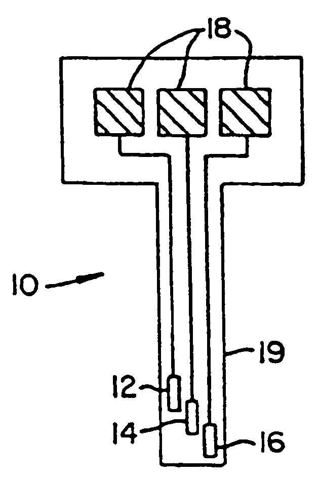
[0019]Embodiments of the invention described herein are based on the discovery that the performance of a sensor, such as a sensor implanted in biological tissue, can be improved by providing a buffer zone around the sensor at the interface with the tissue or fluid to be sampled. Without being bound by a specific scientific theory, it is believed that the buffer zone generated by the sensor systems recited herein stabilizes the reaction conditions by inhibiting alterations in the reaction conditions at the 3-D interface where the analyte reacts with the sensor. Such a buffer zone can be created by placing the sensor inside a tube or cannula, wherein the cannula extends beyond the length of the sensor. One or more apertures in the cannula provide access to the sensor. The configuration of the sensor can be further modified to enhance sensor performance and to adapt the sensor for a particular use.

[0020]All scientific and technical terms used in this application have meanings commonly ...


PUM


Abstract

The disclosure provides a sensor including a sensor having an external surface and a cannula. The cannula comprises a substantially cylindrical wall encircling a lumen, at least one aperture and a distal end. The sensor is positioned within the lumen and the distal end of the cannula extends beyond the sensor. This configuration functions for example to stabilize chemical reactions associated with the sensor by creating a buffer zone between the sensor and the surrounding tissues at the site of implantation. In certain embodiments, the sensor can further comprise an accessory material in proximity to the external surface, wherein the accessory material modifies the biological response of a tissue that is in contact with the sensor. The sensor can also comprise anchors that keeps the sensor in contact with subcutaneous tissue of a subject upon insertion of the sensor into the body of the subject.

Description

CROSS REFERENCE TO RELATED APPLICATIONS[0001]This application is related to commonly owned U.S. patent application Ser. No. 10 / 127,745, filed Apr. 22, 2002, Ser. No. 11 / 301,512, filed Dec. 13, 2005 and Ser. No. 11 / 397,543, filed Apr. 4, 2006, the entire contents of each of which are incorporated herein by reference.TECHNICAL FIELD OF THE INVENTION[0002]This invention relates generally to the manufacture and use of sensor systems suitable for subcutaneous implantation, intravenous use, and other placements involving direct contact between the sensor and the tissue or fluid to be sampled. Such sensor systems are capable of improved performance and stability and a reduction in background noise.BACKGROUND OF THE INVENTION[0003]Biomedical sensors, such as those that utilize enzyme electrodes, can be used to determine the concentrations of a wide variety of analytes and the like rapidly and with considerable accuracy. For example, glucose sensors having enzyme electrodes suitable for in v...

Claims


Application Information

Patent Timeline
IPC IPC(8): A61B5/00
CPCA61B5/14532A61B5/6849A61B5/14865
Inventor SHAH, RAJIVHOSS, UDOSOUNDARARAJAN, GOPIKRISHNANVAN ANTWERP, NANNETTE M.PHAM, BARRY
Owner MEDTRONIC MIMIMED INC
Why Eureka
Try Eureka