
High energy, ultrashort pulse ring fiber laser having a linear dispersion compensator with chirped Bragg gratings

Inactive Publication Date: 2008-01-31
CORNING INC
View PDF6 Cites 26 Cited by
  • Summary
  • Abstract
  • Description
  • Claims
  • Application Information

AI Technical Summary

Benefits of technology

[0012]The use of chirped fiber Bragg gratings as a linear dispersion compensator allows the laser to have an all-fiber architecture, thereby preserving the compact size and freedom from misalignment that fiber lasers offer. Moreover, the use of a pair of serially connected fiber Bragg gratings having substantially equal and opposite dispersions, in combination with a tuner that allows each grating to be individually stretched or compressed, provides a linear dispersion compensator capable of easily adjusting both the net dispersion of the ring laser cavity and the third order dispersion of the cavity to optimize the energy of the pulses.

Problems solved by technology

However, such sapphire-based designs tend to be unstable in operation and relatively large and bulky to implement.
Unfortunately, the power output of the pulse energy generated by such mode-locked fiber lasers has been generally lower than the pulse power available with sapphire or other solid-state laser designs.
However, long fiber cavities create large nonlinearities in the fiber.
Unfortunately, the soliton dynamics in the anomalous dispersion fiber still remains a limitation for further increase of the pulse energy.
While such a design achieves the objective of higher pulse energy, it does so at the expense of losing the main advantages associated with such all-fiber laser designs, i.e., compact size and freedom from misalignment.
Accordingly, there is a need for a mode-locked, all-fiber laser capable of generating high energy, ultrashort pulses without the need for bulk optics which disadvantageously increases the size of the laser, and further provides the potential for misalignment problems.

Method used


Image

  • High energy, ultrashort pulse ring fiber laser having a linear dispersion compensator with chirped Bragg gratings
  • High energy, ultrashort pulse ring fiber laser having a linear dispersion compensator with chirped Bragg gratings
  • High energy, ultrashort pulse ring fiber laser having a linear dispersion compensator with chirped Bragg gratings

Examples


Embodiment Construction

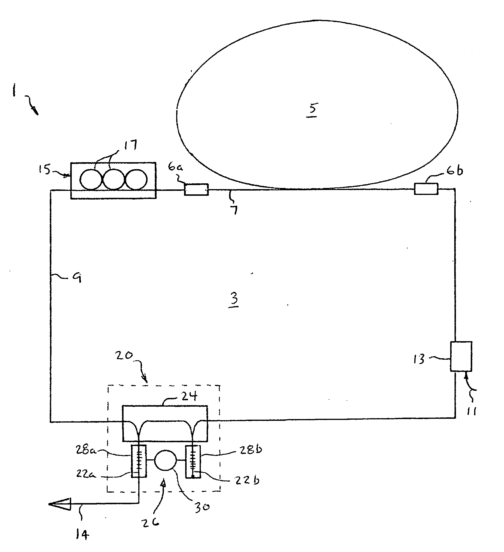
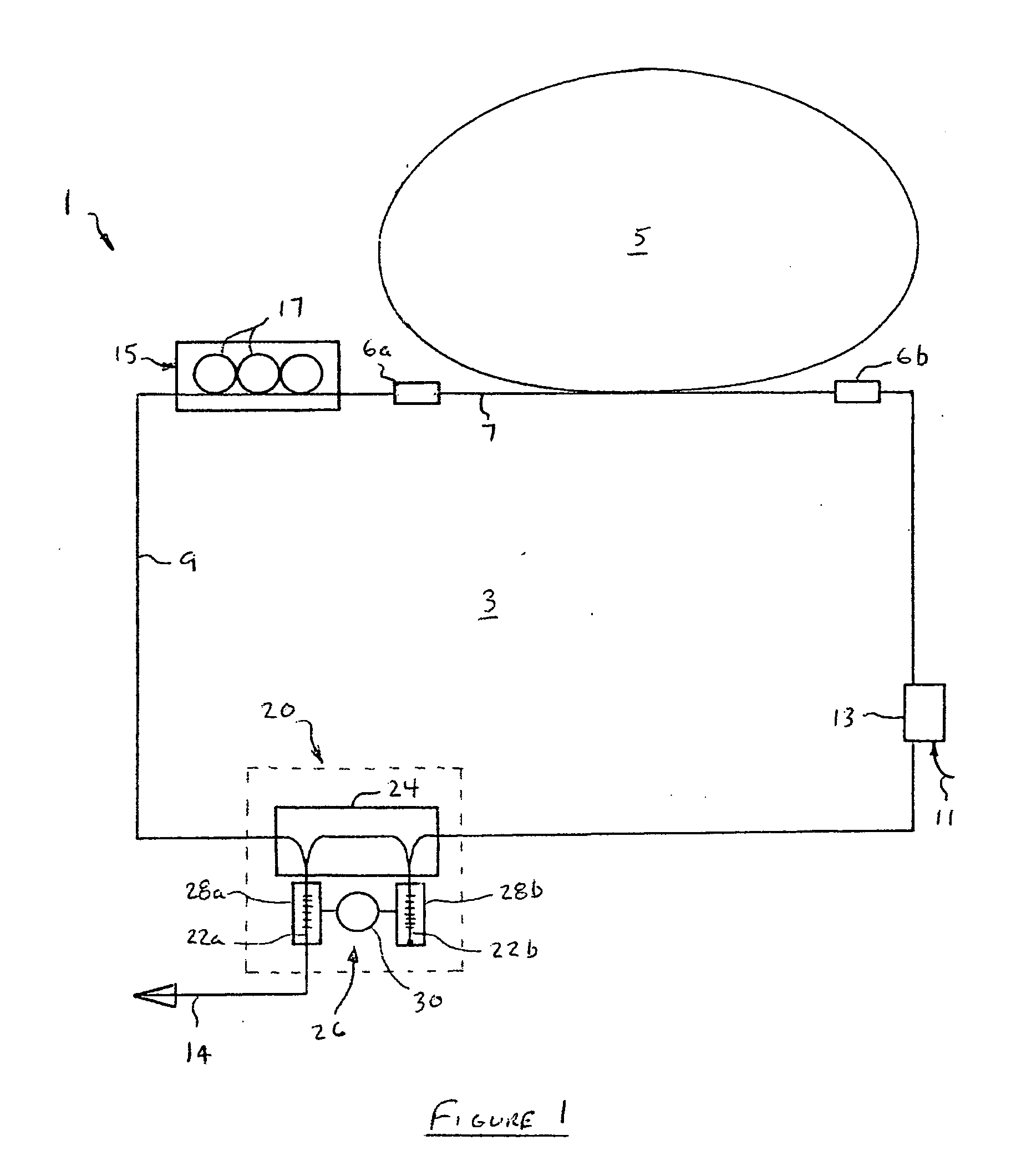
[0019]With reference now to FIG. 1, the high energy, ultrashort pulse fiber laser 1 of the invention consist of a single closed circuit 3 of optical fiber that includes a gain loop 5 connected to the balance of the optical fiber circuit 3 via splices 6a and 6b. The gain loop 5 is formed from a length of optical fiber doped with a gain-producing material. In this particular example, the gain loop 5 is a segment of optical fiber approximately 5 meters long that has been doped with erbium at a concentration of 1700 ppm, although other dopents (such as ytterbium or other rare earth metals) may also be used. Such a length of erbium-doped optical fiber has a dispersion of β2=38.5 ps2 / km, which gives the 5 meter length a total positive dispersion of about 0.193 ps2. Other lengths of doped optical fiber may be used to form the gain loop 5. However, the length of optical fiber should be no less than about 2 meters in order to provide a sufficiently long laser cavity to produce the desired hi...


PUM


Abstract

A high energy, ultra short pulse ring fiber laser is provided that includes a passively mode locked, all optical fiber laser formed from a closed loop of optical fiber doped with erbium or other rare earth metal, a pump light source optically coupled to the loop of optical fiber, and a linear dispersion compensator that includes a pair of chirped Bragg gratings with substantially equal but opposite sign dispersion. The difference in dispersion between the pair of chirped Bragg gratings is adjusted so that it is substantially equal and opposite to the dispersion generated in the loop of optical fiber. The linear dispersion compensator includes a tuner which can individually stretch or compress the pair of chirped fiber Bragg gratings such that one of the gratings can be adjusted to cancel out the dispersion of the ring laser cavity, while the other grating is adjusted to eliminate third order dispersion of the cavity.

Description

BACKGROUND OF THE INVENTION[0001]1. Field of the Invention[0002]This invention generally relates to high energy, ultrashort pulse lasers, and is specifically concerned with a passively mode-locked, all optical ring fiber laser having a linear dispersion compensator that utilizes at least one chirped fiber Bragg grating.[0003]2. Description of the Related Art[0004]Mode-locked, high energy lasers capable of generating femtosecond pulses are known in the prior art. In one such prior art design, lasing is accomplished by means of a titanium doped sapphire crystal, and a Kerr lens mode-locking operation is implemented by a combination of lenses, diffraction gratings, and prisms. However, such sapphire-based designs tend to be unstable in operation and relatively large and bulky to implement.[0005]Mode-locked fiber lasers for generating ultrashort pulses are also known, and offer an attractive alternative to sapphire or other solid-state laser designs due to their greater operational stab...

Claims


Application Information

Patent Timeline
IPC IPC(8): H01S3/30
CPCH01S3/06712H01S3/06725H01S3/0675H01S2301/08H01S3/1053H01S3/1112H01S3/06791
Inventor KUKSENKOV, DMITRI VLADISLAVOVICHLI, SHENPING
Owner CORNING INC
Learn More