
Image forming apparatus, liquid discharging head, image forming method, recorded matter, and recording liquid

a technology of liquid discharging head and image forming apparatus, which is applied in the direction of duplicating/marking methods, inks, printing, etc., can solve the problems of considerable disadvantage in recording speed, record speed, and cost of sheets (recording mediums) to achieve the effect of reducing the phenomenon of beading

Inactive Publication Date: 2008-01-31
RICOH KK
View PDF15 Cites 41 Cited by
  • Summary
  • Abstract
  • Description
  • Claims
  • Application Information

AI Technical Summary

Benefits of technology

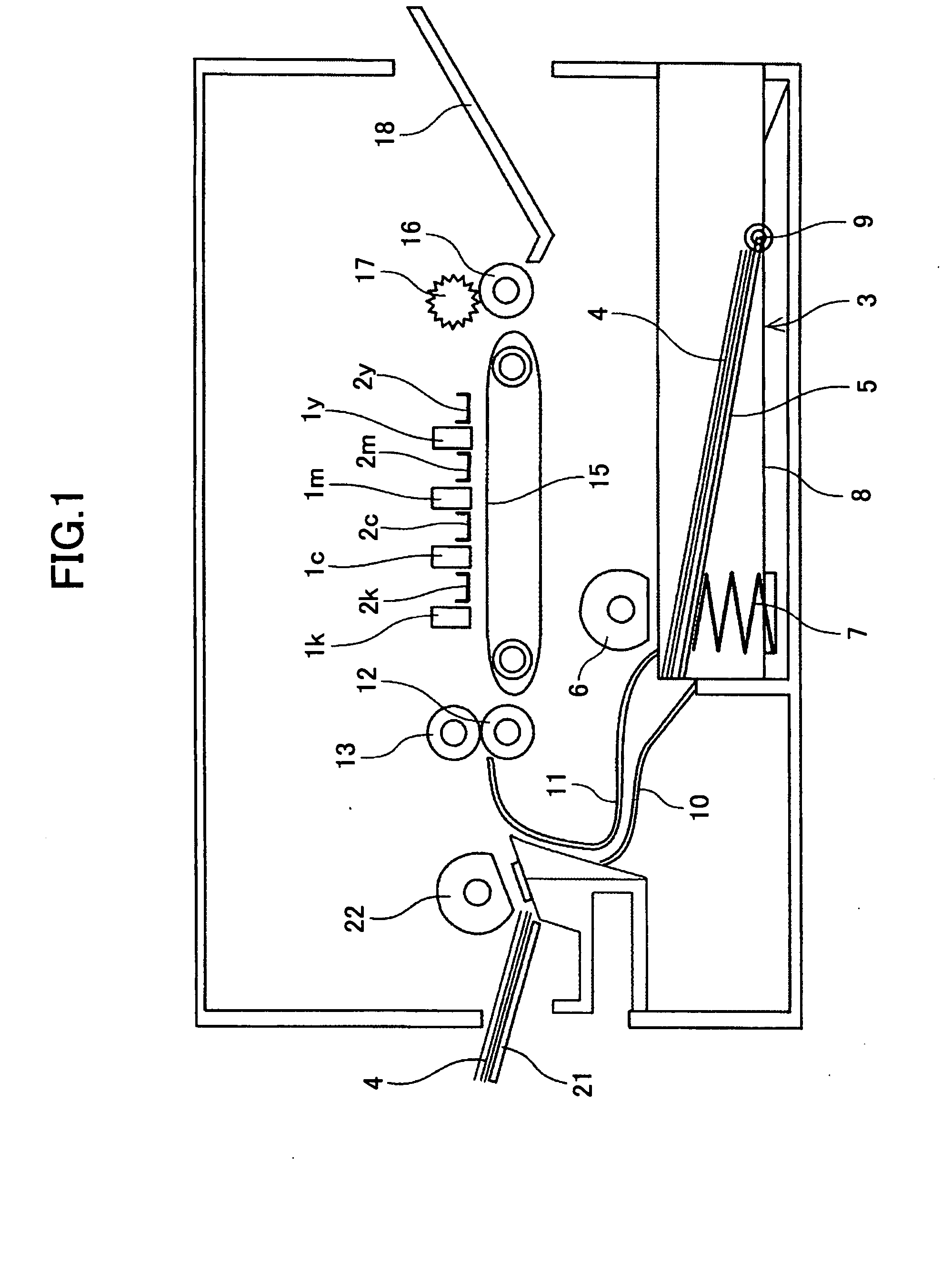
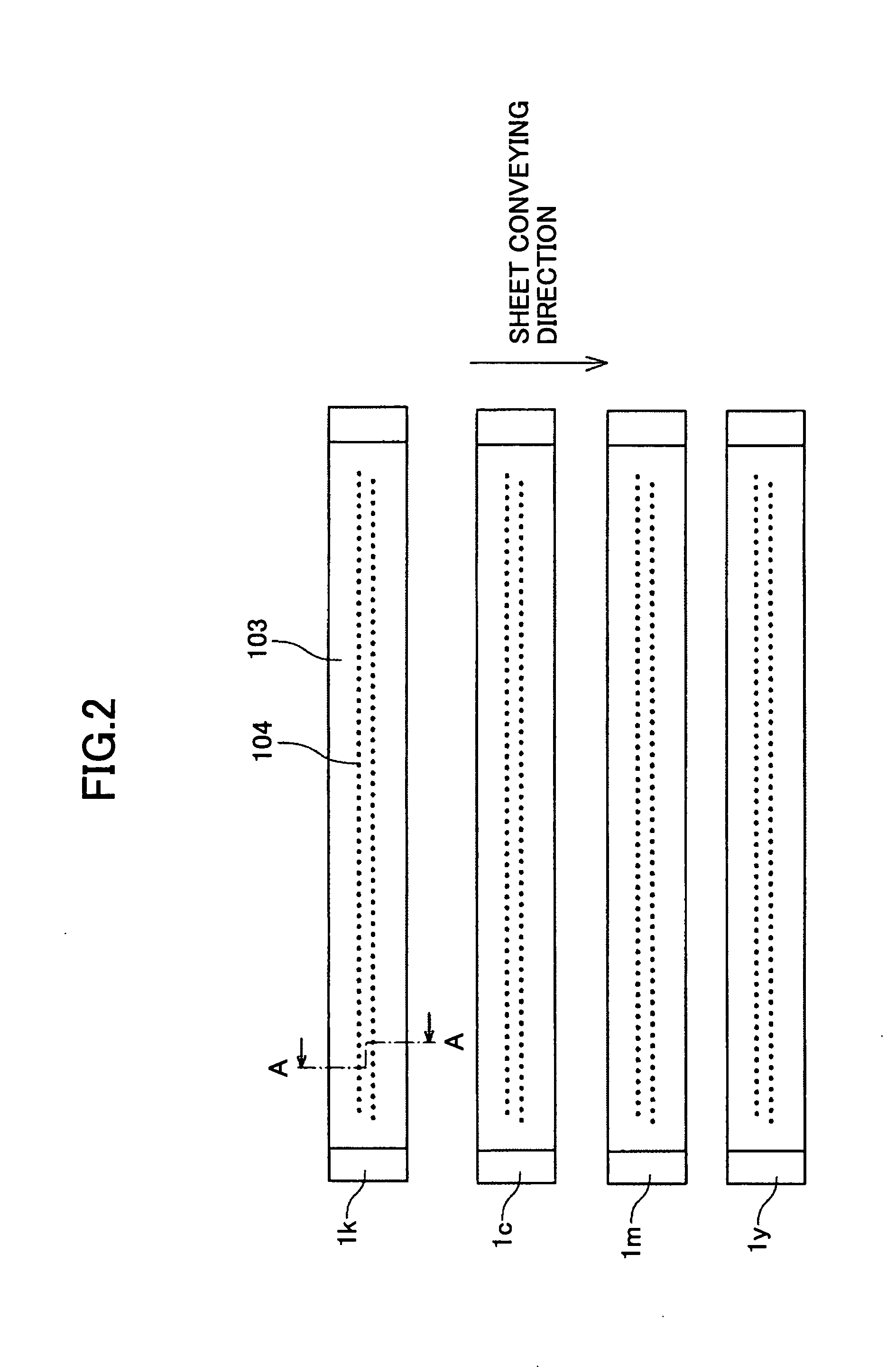
The present invention provides an image forming apparatus, liquid discharging head, image forming method, recorded matter, and recording liquid that overcome the problems of beading and decreased recording speed. The invention includes a line-type liquid discharging head with plural nozzle rows that jet liquid droplets of the same color. The distance between the nozzle rows is set to allow sufficient time for liquid to transfer into the sheet, reducing the beading phenomenon that occurs when dots overlap. The image forming method includes aligning the nozzle rows and adjusting the distance between them to mitigate the beading phenomenon. The recorded matter and recording liquid formed using this invention do not show beading and have improved quality.

Problems solved by technology

The first issue is recording speed.
This is a method of recording with “lines”, which is considerably disadvantageous in terms of recording speed compared to the electrophotographic printing method or the offset printing method of recording in units of pages, i.e., with “planes”.
The second issue pertains to cost of sheets (recording medium).
However, inkjet-dedicated paper is generally expensive, and therefore, offices subjected to severe cost cutting are hesitant to purchase such sheets.
Furthermore, in cases of printing for commercial purposes where a large amount of printouts are required, it is extremely disadvantageous if high-quality images can be achieved only with inkjet-dedicated paper.
The permeation process is accompanied by various problems and restrictions.
However, this does not apply to every type of sheet.
In particular, on sheets that cannot sufficiently absorb ink, the overflowing unabsorbed ink often becomes solid and forms undesirable irregularities (beading phenomenon).
However, in the line-type inkjet recording apparatus where recording speed is given high priority, it is difficult to provide enough waiting time for drying.
Although it is possible to decrease the recording speed and the sheet conveying speed even in the line-type inkjet recording apparatus so as to provide sufficient drying time, this runs counter to the original purpose of the line-type inkjet recording apparatus of increasing the recording speed.
As a result, the sheet may be soiled, or in the worst case, the sheet may become caught in the heads and cause a paper jam that would stop the mechanism.
Meanwhile, in the multi-path recording method described in patent document 3, the high speed of the line-type inkjet recording apparatus is disadvantageously decreased.

Method used


Image

  • Image forming apparatus, liquid discharging head, image forming method, recorded matter, and recording liquid
  • Image forming apparatus, liquid discharging head, image forming method, recorded matter, and recording liquid
  • Image forming apparatus, liquid discharging head, image forming method, recorded matter, and recording liquid

Examples


adjustment example 1

[0244] -Adjustment of Polymer Microparticle Dispersing Element Including Copper Phthalocyanine Pigment-

[0245] Oxygen in a 1 liter flask provided with a mechanical stirrer, a thermometer, a nitrogen gas introduction tube, a circulating tube, and a dropping funnel was thoroughly replaced with nitrogen gas. Then, styrene 11.2 g, acrylic acid 2.8 g, lauryl methacrylate 12.0 g, polyethylene glycol methacrylate 4.0 g, styrene macromer (manufactured by TOAGOSEI CO., LTD., product name: AS-6) 4.0 g, and mercaptoethanol 0.4 g were provided in the flask, and heated to 65° C. Next, a mixed solution of styrene 100.8 g, acrylic acid 25.2 g, lauryl methacrylate 108.0 g, polyethylene glycol methacrylate 36.0 g, hydroxyethyl methacrylate 60.0 g, styrene macromer (manufactured by TOAGOSEI CO., LTD., product name: AS-6) 36.0 g, mercaptoethanol 3.6 g, azobis dimethyl valero nitrile 2.4 g, and methyl ethyl ketone 18 g was dropped into the flask over a period of 2.5 hours.

[0246] When the dropping oper...

adjustment example 2

[0249] -Adjustment of Polymer Microparticle Dispersing Element Including Dimethyl Guinacridone Pigment-

[0250] The copper phthalocyanine pigment of adjustment example 1 was replaced with C.I. pigment red 122. Otherwise, a magenta polymer microparticle dispersing element was adjusted in the same manner as adjustment example 1.

[0251] The achieved polymer microparticles had an average particle diameter (D 50%) of 127 nm, measured with a particle size distribution measuring device (Microtrac UPA, manufactured by NIKKISO CO., LTD.).

adjustment example 3

[0252] -Adjustment of Polymer Microparticle Dispersing Element Including Monoazo Yellow Pigment-

[0253] The copper phthalocyanine pigment of adjustment example 1 was replaced with C.I. pigment yellow 74. Otherwise, a yellow polymer microparticle dispersing element was adjusted in the same manner as adjustment example 1.

[0254] The achieved polymer microparticles had an average particle diameter (D 50%) of 76 nm, measured with a particle size distribution measuring device (Microtrac UPA, manufactured by NIKKISO CO., LTD.).


PUM

PropertyMeasurementUnit
RHaaaaaaaaaa
surface tensionaaaaaaaaaa

Abstract

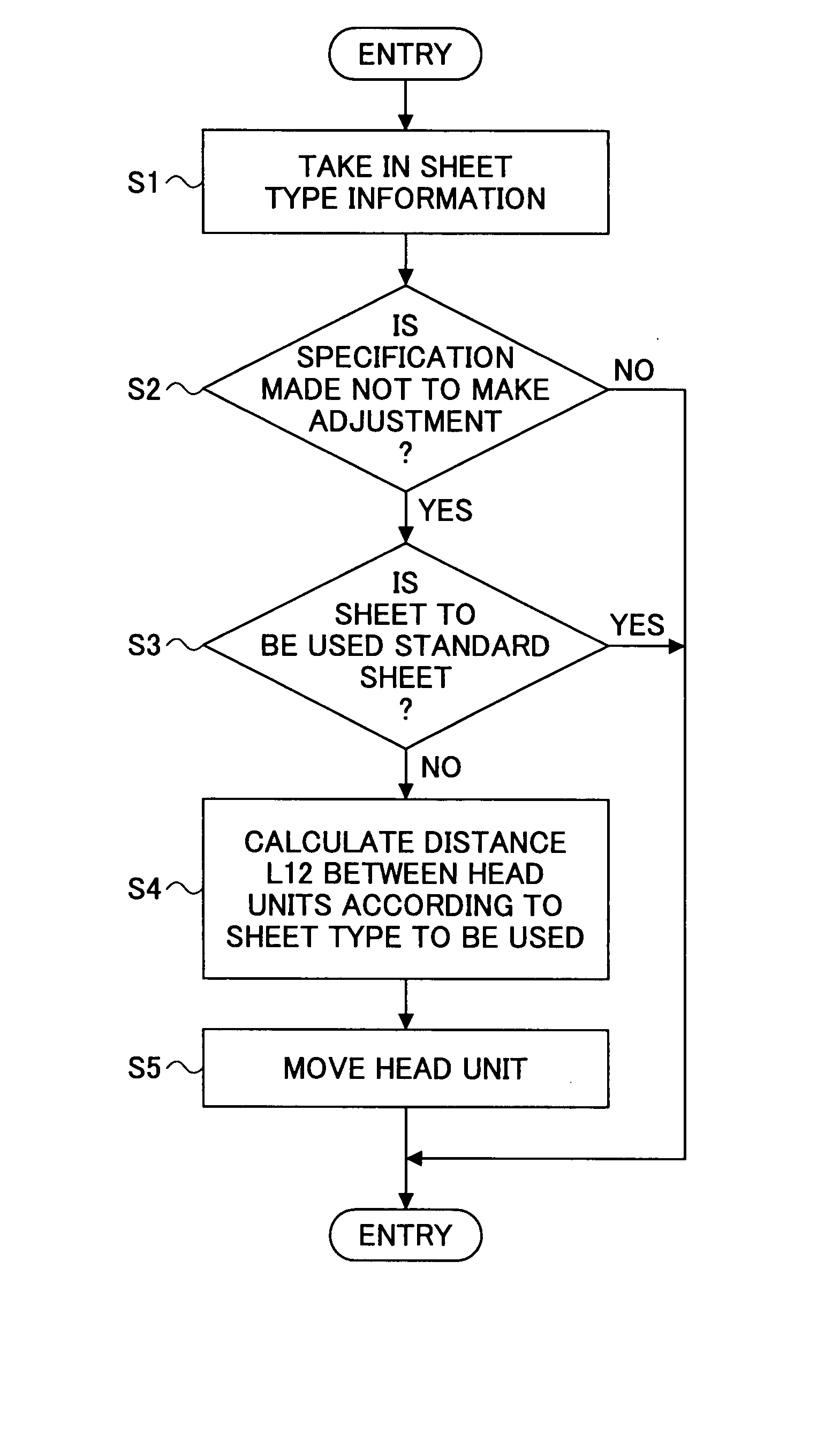
A disclosed image forming apparatus includes a line-type liquid discharging head including nozzles configured to jet liquid droplets. The nozzles are aligned in a sheet width direction. The line-type liquid discharging head includes plural nozzle rows each including an alignment of a plurality of the nozzles configured to discharge liquid droplets of the same color. A distance L1 between the nozzle rows is L1=T11×V1, where T1 is a liquid transfer amount impregnating time of a standard sheet and V1 is a sheet conveying speed.

Description

BACKGROUND OF THE INVENTION [0001] 1. Field of the Invention [0002] The present invention relates generally to image forming apparatuses, liquid discharging heads, image forming methods, recorded matter, and recording liquid. [0003] 2. Description of the Related Art [0004] Generally, printers, facsimile machines, copiers, plotters, and image forming apparatuses in which plural functions of the aforementioned devices are combined in a single apparatus are configured to perform image formation (recording, printing, imaging, character printing are also used as synonyms). One method of image formation is performed by using a liquid discharging device including a recording head configured with a liquid discharging head that discharges (jets) liquid droplets of recording liquid (hereinafter, also referred to as “ink”). The recording liquid is caused to adhere to a medium (hereinafter, also referred to as a “sheet” made of any material; recording medium, transfer material, recording sheet ...

Claims


Application Information

Patent Timeline
Patent Type & Authority Applications(United States)
IPC IPC(8): B41J29/38B41J2/01B41M5/00C09D11/00
CPCB41J2/055B41J2/155C09D11/322B41J11/009B41J2002/14419B41J2/2107
Inventor HIRANO, MASANORIOHTA, YOSHIHISAYOSHIDA, MASAKAZUKIMURA, SHIGEAKIMOROHOSHI, NAOYAINOUE, TOMOHIROYOSHIDA, TAKAHIRO
Owner RICOH KK
Learn More