
Method and apparatus for production of meltblown nanofibers

a nanofiber and meltblown technology, applied in the field of polymer nanofiber production methods and apparatuses, can solve the problems of limited commercial application of nanofibers, low production rate of this process, and inability to have wide commercial application, and achieve low cost, high production rate, and low throughput or polymer flow rate

Active Publication Date: 2008-01-31
HILLS CO
View PDF12 Cites 56 Cited by
  • Summary
  • Abstract
  • Description
  • Claims
  • Application Information

AI Technical Summary

Benefits of technology

[0010] It is another object of the invention to provide an improved plate edge orifice spinneret capable of producing nanofibers of the same size and the same or better quality as those produced using electrospinning techniques, at higher production rates, lower cost, and without the need to deal with noxious fumes.
[0016] The present invention enhances meltblown technology of the type described in the aforementioned Berger patent to allow production of a nonwoven web with the same size nanofibers as those produced by electrospinning processes. The end product is the same but the production rate is much higher, the cost is much lower and there are no byproduct noxious fumes. In addition, a greater variety of polymers can be used without extensive machine modifications. With the present invention, webs can be made with most of the fibers less than 0.5 micron in diameter and at production rates of 1.5 kg / meter / hour or higher.

Problems solved by technology

These advantages notwithstanding, nanofibers have had limited commercial applicability, primarily because the production costs are too high.
The production rate of this process is very low and is typically measured in grams per hour, much too low to have wide commercial applicability.
Moreover, the concentration of polymer in the solvent tends to be low (on the order of 10%) thereby further reducing the effective production rate and, if the system is operated at high volume, the operator is forced to contend with significant amounts of solvent and noxious off-gas byproducts.
Further, switching the type of polymer that can be used in this process typically requires extensive machine modifications
Conventional meltblown spinning technology is limited to two microns because of the inability to make sufficiently small spin holes (i.e., spinning orifices).

Method used


Image

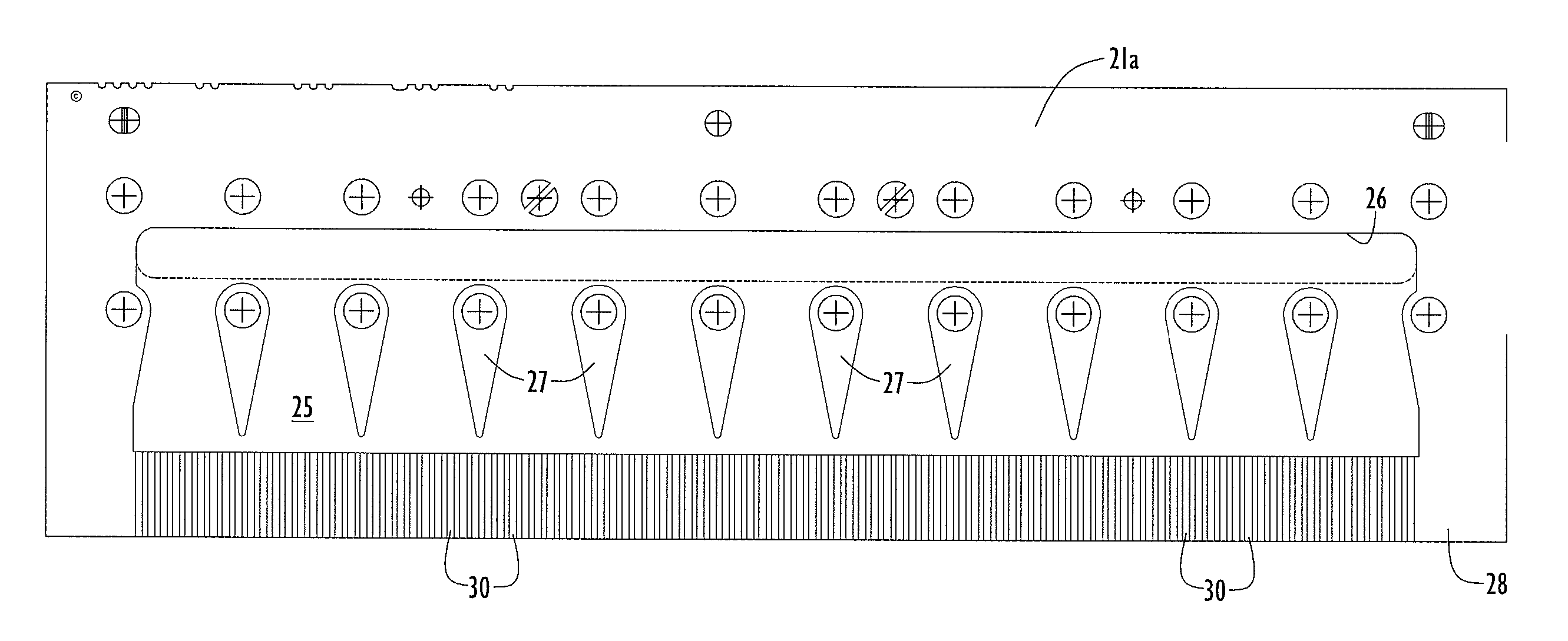
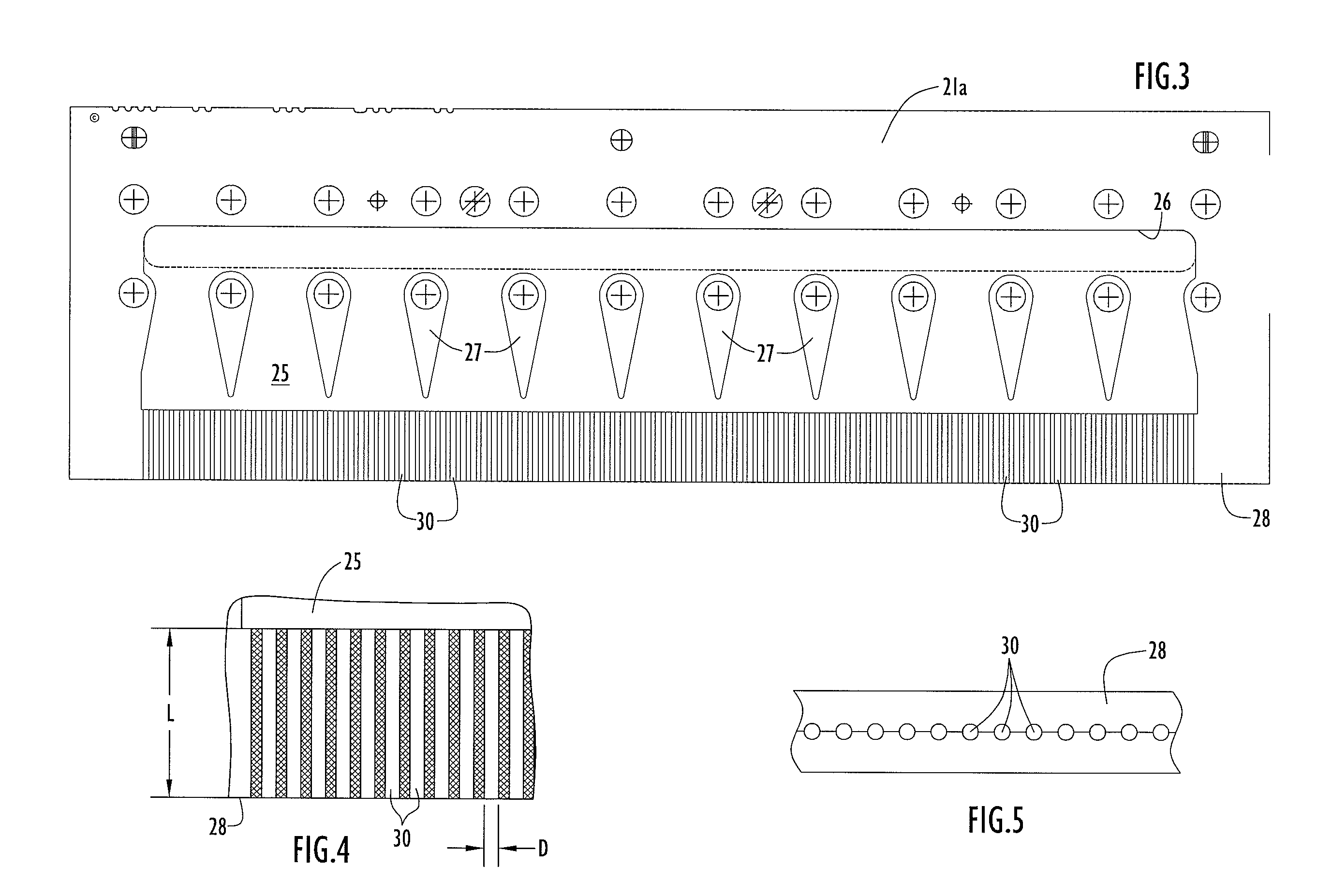
  • Method and apparatus for production of meltblown nanofibers
  • Method and apparatus for production of meltblown nanofibers
  • Method and apparatus for production of meltblown nanofibers

Examples


Embodiment Construction

[0023] The following detailed explanations of the drawings and of the preferred embodiments reveal the methods and apparatus of the present invention.

[0024] Referring more specifically to the drawings, a pump 10 delivers molten polymer received from a polymer inlet 11 to pump block 13 where the polymer is metered and delivered to an inlet manifold 15 of a meltblown spinneret pack 17. The meltblown spinneret pack 17 comprises a first block 19 and a second block 20 secured in close relation to one another along respective surfaces and to respective air jet blocks 23, 24 proximate the downstream or outflow end of the unit.

[0025] Between blocks 19 and 20 there is a thin plate spinneret 21 which, in the preferred and illustrated embodiment, comprises two thin plates 21a and 21b joined flush against one another in any suitable manner. Thin plates 21a and 21b have shallow channels and passages etched or otherwise formed in their abutting surfaces in a pattern that is the same for both pl...


PUM

PropertyMeasurementUnit
Thicknessaaaaaaaaaa
Thicknessaaaaaaaaaa
Diameteraaaaaaaaaa

Abstract

A method and apparatus for producing polymeric nanofibers utilizes a meltblown spinneret die having spin holes formed by grooves in plate(s) surface(s) of plate(s) where polymer exits at the plate(s) edge(s). The grooves are smaller than 0.005″ wide×0.004″ deep and have an L / D at least as large as 20:1. Flow rates of polymer through the apparatus are very low, on the order of 0.01 ghm or less. The method / apparatus produces may also be viewed as including A meltblown fabric having fibers mostly less than 0.5 microns in diameter is produced.

Description

CROSS REFERENCE TO RELATED APPLICATION [0001] This application claims priority from U.S. Provisional Patent Application Ser. Nos.: [0002] (a) 60 / 792,671 entitled “Spin Pack With Long Small Holes,” filed Apr. 18, 2006; and [0003] (b) 60 / 894,939, entitled “Nanofiber Meltblown Production Method, Process & Apparatus”, filed Mar. 15, 2007. The disclosures in these provisional patent applications are incorporated herein by reference in their entireties.FIELD OF THE INVENTION [0004] The present invention pertains to improved methods and apparatus for producing polymeric nanofibers and, more particularly to improvements in meltblown technology that permit production of polymeric nanofibers of small cross-section at a rate suitable for commercial operation. The invention also encompasses webs and fabrics produced by the aforesaid methods and apparatus. BACKGROUND [0005] As commonly used in discussing polymeric fibers, “nanofibers” refers to fibers with “diameters” (i.e., maximum transverse ...

Claims


Application Information

Patent Timeline
IPC IPC(8): B29C39/14B29C48/05
CPCD01D5/0985D01D4/025B29C48/05B29C48/911B29C48/2515B29C48/2556
Inventor BRANG, JAMES E.WILKIE, ARNOLDHAGGARD, JEFF SCOTT
Owner HILLS CO
Learn More