
Power supply system using delay lines in regulator topology to reduce input ripple voltage

Inactive Publication Date: 2008-01-24
IBM CORP
View PDF2 Cites 9 Cited by
  • Summary
  • Abstract
  • Description
  • Claims
  • Application Information

AI Technical Summary

Benefits of technology

[0011]As a result of the summarized invention, technically we have achieved a solution that reduces

Problems solved by technology

In such designs, voltages must be limited to values below the breakdown rating of the switches and rectifiers, and finite inductances are inevitable.
Given the low voltage, high current and finite inductance requirements, switching or commutation of current requires time.
The commutation time increases in direct proportion to the magnitude of the current and, in practical designs, is limited to a small percentage of the overall cycle time.
Thus, the maximum operating frequency of current switching regulators is limited by the current, voltage and inductance parameters in the circuit.
In particular, as electrical designs become more complex the need for multiple DC to DC voltage regulators on a single card increases.
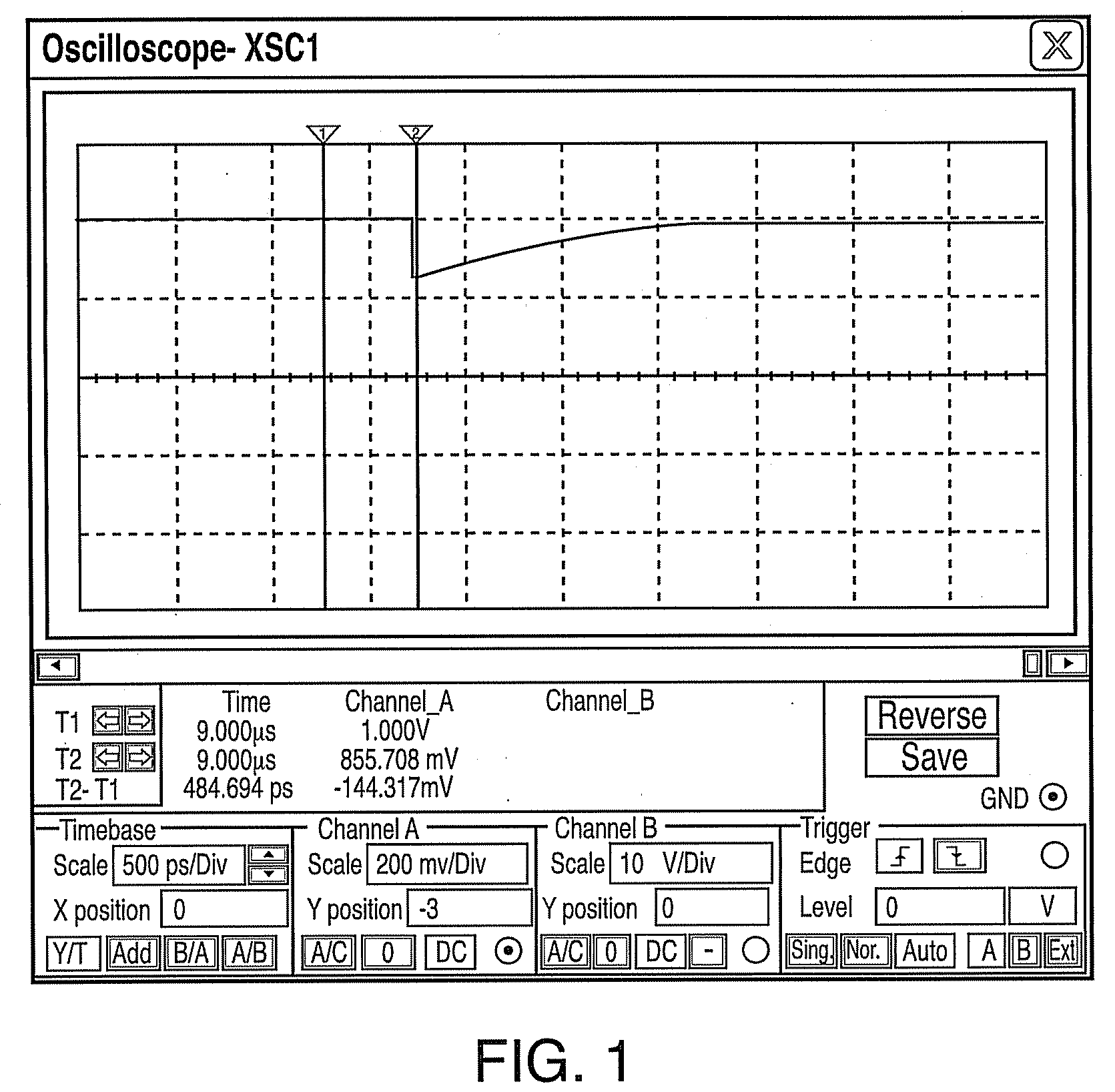
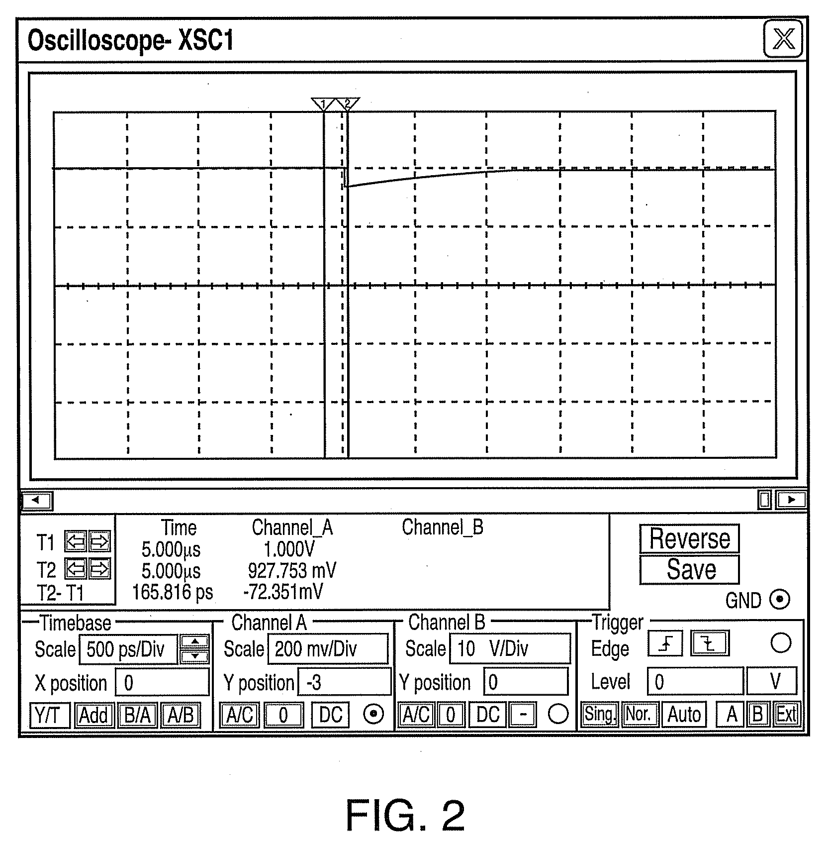
The basic problem with these regulators, however, is that they create voltage ripple on the main input voltage due to topology of the regulator.
However, this has significant physical and space limitations.
At such high switching frequencies (high switching frequencies are used to reduce capacitor size) layout becomes extremely important and it is not physically possible to place the capacitors close enough to the regulator to combat the noise.
Thus, it is well known that switching regulators create high voltage ripple on the main input voltage.
However, adding capacitance has significant physical and space limitations.

Method used


Image

  • Power supply system using delay lines in regulator topology to reduce input ripple voltage
  • Power supply system using delay lines in regulator topology to reduce input ripple voltage
  • Power supply system using delay lines in regulator topology to reduce input ripple voltage

Examples


Embodiment Construction

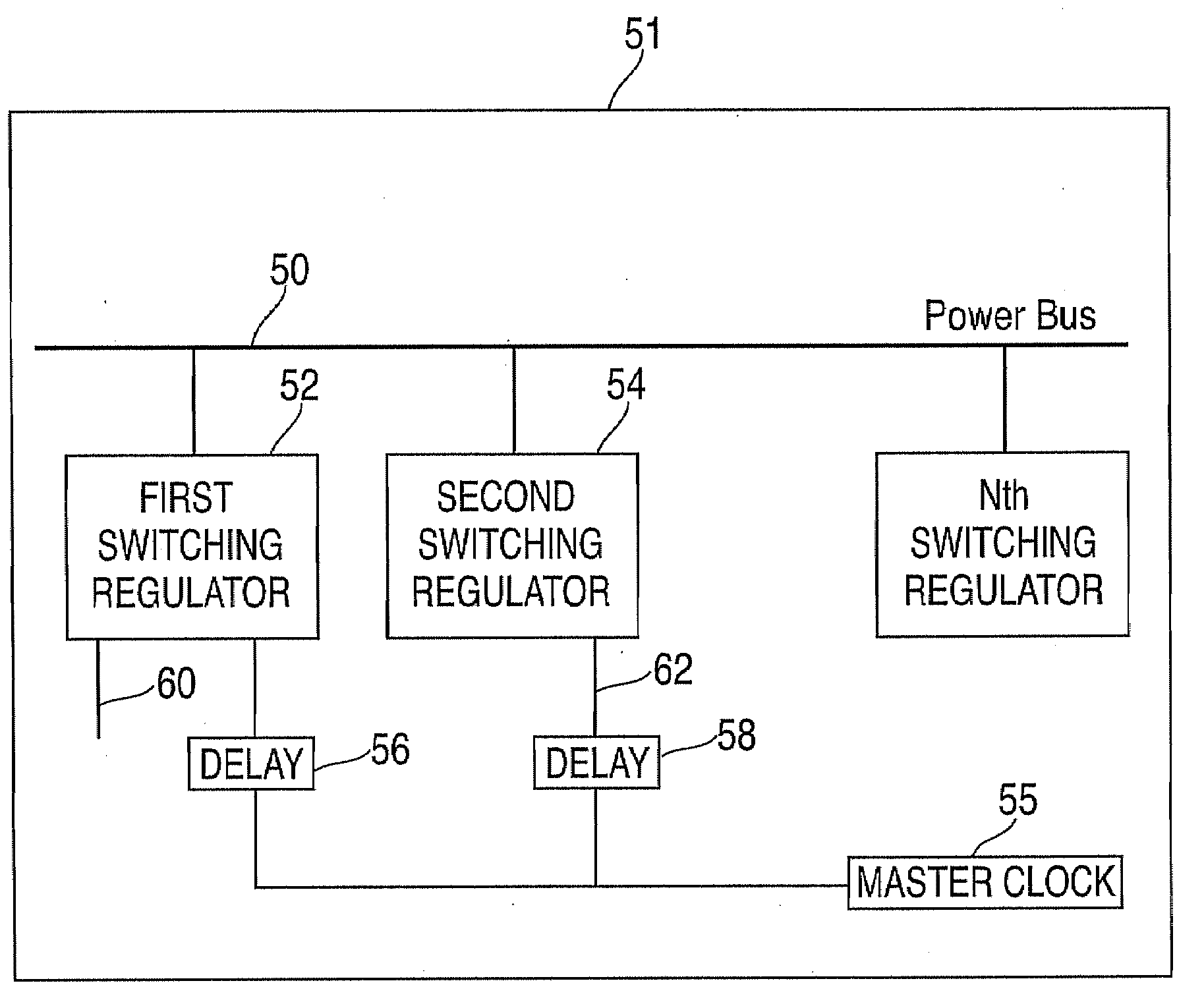
[0018]One aspect of the exemplary embodiments is a method for reducing voltage ripple in switching regulators. Another aspect of the exemplary embodiments is a method for reducing input voltage ripple in switching regulators by adding a delay line to the synchronization input pin of one or more switching regulators.

[0019]There are two types of regulators, one is a linear regulator and the other is a switching regulator. Switching regulators are more efficient than linear regulators because switching regulators transform power while linear regulators consume power to regulate. Also, switching regulators store-up energy in a magnetic field and recover the energy when the magnetic field collapses. They also radiate considerable EMI (Electro-Magnetic Interference) as a result of inductor high current switching. Finally, switching regulators are usually used in applications involving high power and where efficiency is of primary concern.

[0020]The switching regulator is nothing more than ...


PUM


Abstract

A power supply system for reducing input ripple voltage, the system including: a first switching regulator having at least two input pins, one input pin being a voltage input pin and another input pin being a synchronization input pin; a second switching regulator having at least two input pins, one input pin being a voltage input pin and another input pin being a synchronization input pin; wherein outputs of the first switching regulator and the second switching regulator are connected to a power bus; a first delay element connected to the synchronization input pin of the first switching regulator; a second delay element connected to the synchronization input pin of the second switching regulator; wherein the first delay element and the second delay element have different delays, the first switching regulator and second switching regulator operating out of phase; and a master clock for providing timing control to the first and second delay elements.

Description

TRADEMARKS[0001]IBM® is a registered trademark of International Business Machines Corporation, Armonk, N.Y., U.S.A. Other names used herein may be registered trademarks, trademarks or product names of International Business Machines Corporation or other companies.BACKGROUND OF THE INVENTION[0002]1. Field of the Invention[0003]This invention relates to a switching regulator, and particularly to a method of adding a delay line to the synchronization input of the switching regulator to reduce the input ripple voltage.[0004]2. Description of Background[0005]It is well known in the switching regulator art that operation at higher frequencies leads to smaller size, weight, etc. To achieve high frequency with its associated high power and current, it is necessary to make the physical packaging of the transformer and rectifiers as small as possible due to current switching in the transformer windings and rectifiers. In such designs, voltages must be limited to values below the breakdown rat...

Claims


Application Information

Patent Timeline
IPC IPC(8): G05F1/00
CPCH02M2001/008H02M1/15H02M1/008
Inventor CAGNO, BRIAN J.ELLIOTT, JOHN C.GARCIA, ENRIQUE Q.
Owner IBM CORP
Learn More