
Safety relief valve having a low blow-down value and spring therefore

a safety relief valve and low blow-down value technology, applied in the field of safety relief valves, can solve the problems of no longer sonic flow out of the secondary orifice, and achieve the effects of preventing built-up downstream back pressure, low blow-down value, and low blow-down valu

Inactive Publication Date: 2008-01-24
MERCER VALVE
View PDF48 Cites 4 Cited by
  • Summary
  • Abstract
  • Description
  • Claims
  • Application Information

AI Technical Summary

Benefits of technology

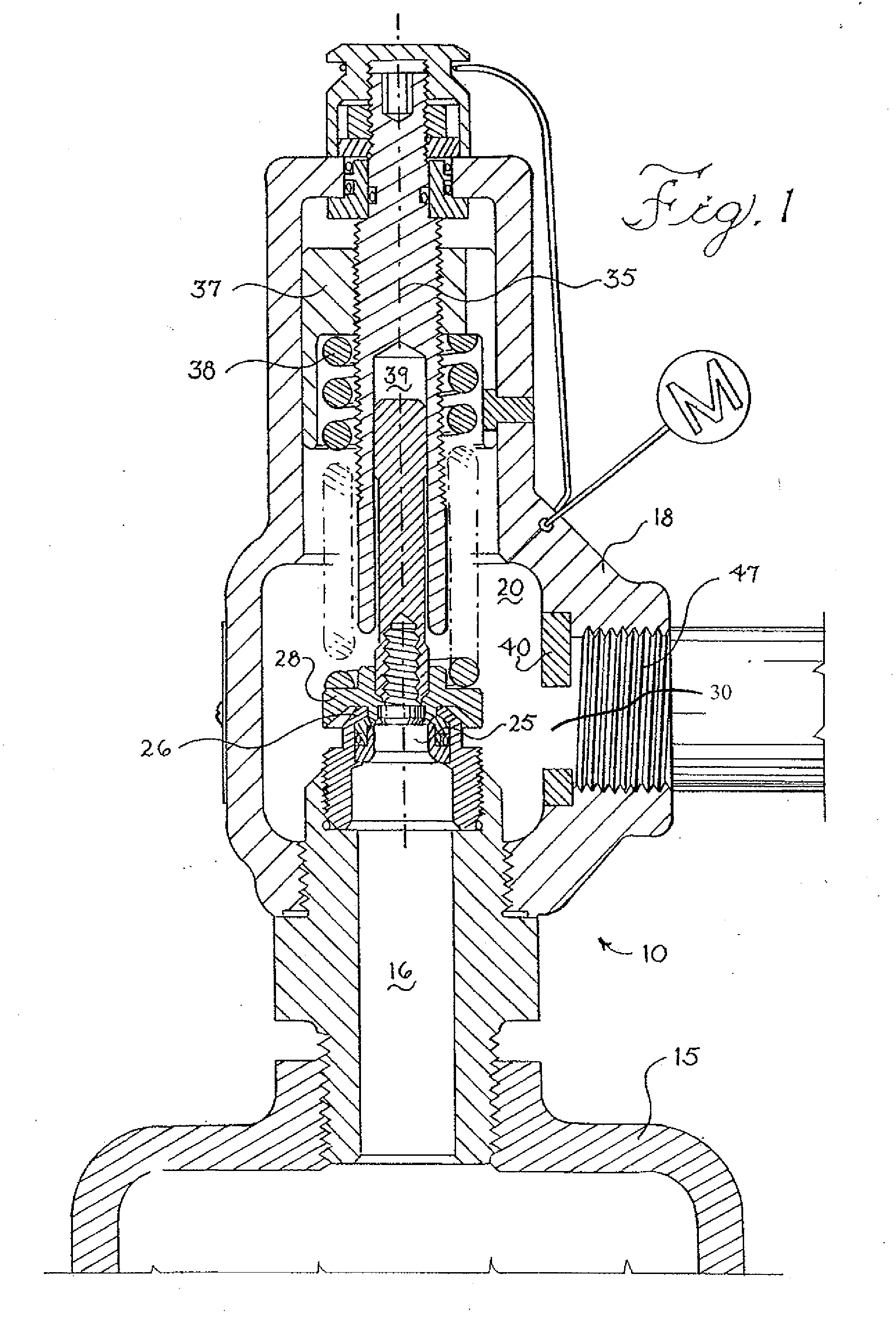
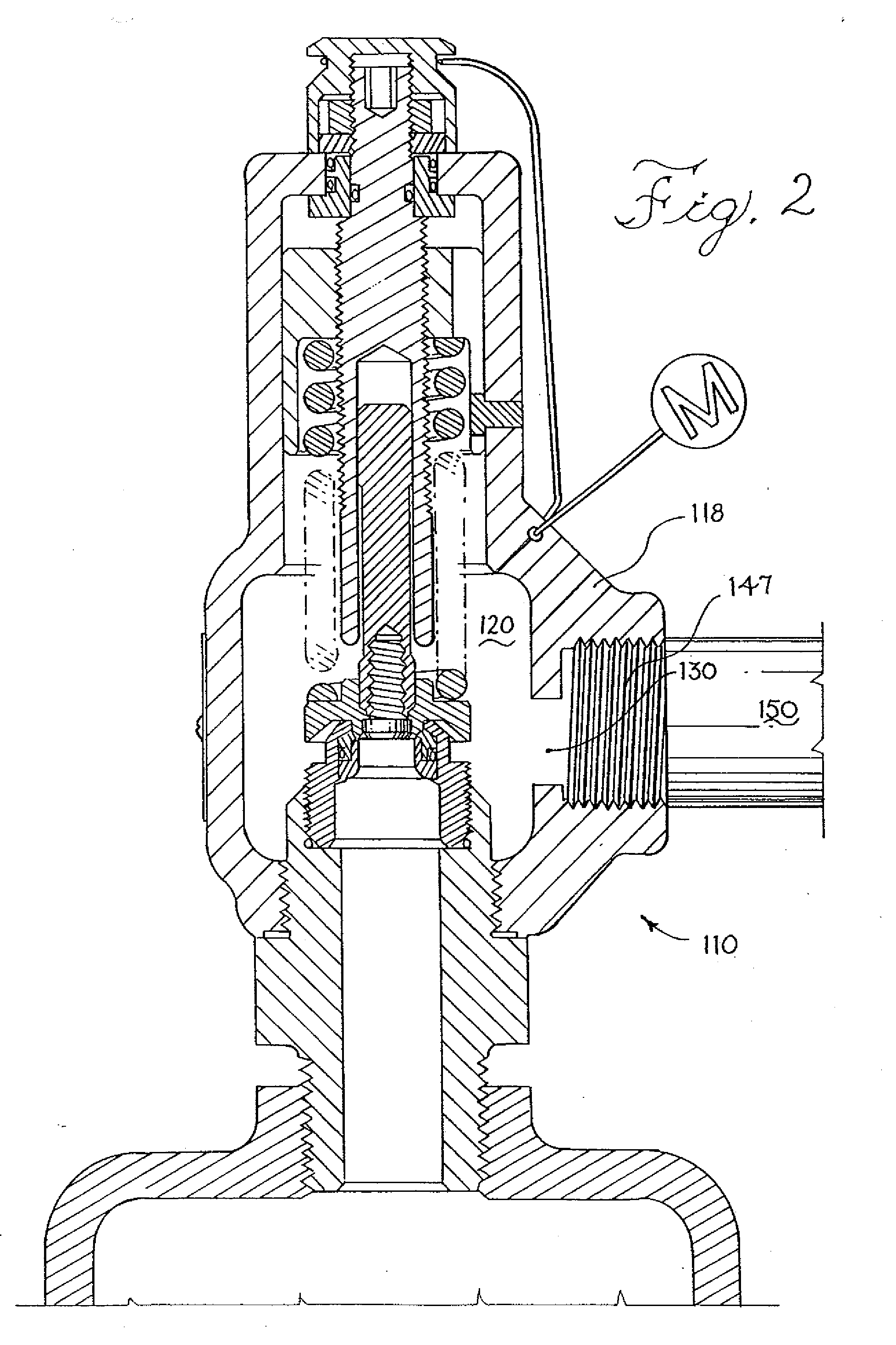
[0019] A snap-type safety relief valve has been discovered that addresses the problems left unsolved by prior valves. Namely, it has been discovered that a snap-type safety relief valve having sonic flow into the body of the valve and out of a secondary orifice on the valve prevents built-up downstream back pressures from affecting the low blow-down value of the valve. This means that the addition of longer outlet piping on the valve, within limits, will not change the low blow-down value of the valve. Thus, the low blow-down value of the valve is consistent. If an excessive length of piping is added, however, then the flow out of the secondary orifice will no longer be sonic, and the blow-down value will be subject to built-up downstream back pressures. Nevertheless, so long as the flow into the body of the valve and out of the secondary orifice of the valve is sonic, built-up downstream back pressures are prevented from counteracting the forces keeping the valve open. The snap-type safety relief valve of the present invention preferably has a high flow co-efficient, and is easy and inexpensive to use and manufacture.
[0020] Also, it has been discovered that if spring rate tolerances are reduced from +7% to +2%, the number of different springs for a given valve design can be reduced from approximately 40 to 20. Furthermore, standard spring ranges can be established and documented to vastly improve the manufacturing process and also assist field servicing. Thus an improved safety relief valve using commercially available springs modified by various methods is also the subject of the present application.
[0027] In still another aspect of the invention, an improved low blow-down snap-type safety relief valve is provided. The valve has an inlet, a disk member closable on the inlet, a mechanism biasing the disk member on the inlet, a body, and an outlet. The valve prevents built-up downstream back pressures from changing a blow down value. The improvement on the valve comprises a secondary orifice in the body of the safety relief valve sized to permit gas to escape from the body through the secondary orifice in a sonic flow when the valve is opened during testing under operating conditions specified for the use of the valve.

Problems solved by technology

If an excessive length of piping is added, however, then the flow out of the secondary orifice will no longer be sonic, and the blow-down value will be subject to built-up downstream back pressures.

Method used


Image

  • Safety relief valve having a low blow-down value and spring therefore
  • Safety relief valve having a low blow-down value and spring therefore
  • Safety relief valve having a low blow-down value and spring therefore

Examples


Embodiment Construction

Determining the Size of a Secondary Orifice

[0072] Referring to FIG. 6, a non-limiting example is provided to show a preferred method for experimentally determining what size to make a secondary orifice 430 in a trial snap-type low blow-down safety relief valve 410.

[0073] The trial snap-type low blow-down safety relief valve 410 is designed for specified operating conditions. For example, the trial snap-type low blow-down safety relief valve 410 may be designed to operate with a maximum length of from about 15 feet to about 20 feet of outlet piping 450 having one elbow (not shown). The outlet piping 450 is of the type with schedule number 80, since this is the most common seamless pipe for the pressure ranges addressed in this non-limiting example. The trial snap-type low blow-down safety relief valve 410 may also be designed for a set pressure of 100 psia that will relieve air from a pressurized system when the pressures therein exceed the set pressure. In a typical scenario, the ...


PUM

PropertyMeasurementUnit
pressureaaaaaaaaaa
pressureaaaaaaaaaa
pressureaaaaaaaaaa

Abstract

A safety relief valve is provided that comprises a body comprising a chamber therein and an inlet and an outlet, the inlet comprising an inlet valve seat; a disk member closable on the inlet valve seat; and a mechanism in the body biasing the disk member to rest on the inlet valve seat with a set force such that when the pressure in the inlet exceeds a set pressure resulting from the set force, the disk member is lifted from the inlet valve seat, the mechanism comprising a combination of a coil spring and one or more disk springs stacked in series with the coil spring. A method of preparing a coil spring for use in a pressure relief valve comprises measuring the spring rate of the coil spring and; modifying the spring so as to modify its spring rate to be within ±2% of a desired spring rate.

Description

REFERENCE TO EARLIER FILED APPLICATIONS [0001] The present application is a divisional of application Ser. No. 10 / 601,304, filed Jun. 20, 2003, which is a continuation-in-part of U.S. patent application Ser. No. 10 / 364,290, filed Feb. 10, 2003, which is a continuation-in-part of U.S. patent application Ser. No. 09 / 885,293, filed Jun. 19, 2001, now U.S. Pat. No. 6,516,828, all of which are hereby incorporated by reference in their entirely.BACKGROUND [0002] The present invention relates to safety relief valves for use on a pressurized system such as pressure vessel or a flow line, especially snap-type safety relief valves having a consistent low blow-down value, springs for safety relief valves and methods of manufacturing safety relief valves. [0003] Spring operated relief valves are used to protect pressurized systems from pressures that exceed their maximum allowable working pressure or any pressures that the user specifies. Most spring operated relief valves use an externally adj...

Claims


Application Information

Patent Timeline
Patent Type & Authority Applications(United States)
IPC IPC(8): F16K17/04F16K37/00
CPCF16K17/04Y10T29/49412F16K37/0083F16K17/0493Y10T137/7905Y10T137/0497Y10T137/7929Y10T137/6086Y10T137/7738
Inventor CHOATE, JEREMYEASTON, MICHAELTAYLOR, WESLEY
Owner MERCER VALVE
Learn More