Mounting board

a technology of mounting boards and earpieces, which is applied in the direction of machine supports, machine frames, casings, etc., can solve the problems of increased likelihood of accidental impact, difficult to ensure that the die is properly filled, and sensitive earpieces to impact, so as to reduce the number of engine components

Inactive Publication Date: 2008-01-24
VOLVO PENTA AB
View PDF8 Cites 1 Cited by
  • Summary
  • Abstract
  • Description
  • Claims
  • Application Information

AI Technical Summary

Benefits of technology

[0006] By configuring the ear portion as an essentially flat rigid plate which is releasably attached to the engine block in a vertically extending position in relation to the crank shaft, the difficulty of casting of the engine block is substantially diminished. Furthermore, in the event of an accidental impact with a dislocation of the ear portion as a result, the engine block does not have to be rejected since the ear portion could be reinstalled in a correct position.
[0008] In a preferred embodiment, the flat rigid plate is attached to the engine block in a position along the length of the crank shaft such that the power take off and a drive wheel, mounted on the mounting bracket and arranged for propulsion of the auxiliary device, are arranged in a single plane and vertically extending in relation to the crank shaft. This configuration provides for a simple transmission between the drive wheel arranged on the mounting bracket and the crank shaft, since both would be arranged in a single plane.
[0011] In another preferred embodiment, a reduction in the number of engine components is achieved by: extending the flywheel casing, forming a housing for the fly wheel, integrally forming a housing for at least a drive wheel of the auxiliary device, and closing the housing for at least a drive wheel of the auxiliary device with the essentially flat rigid plate.

Problems solved by technology

This is a considerable disadvantage with regard to manufacturing engineering, and in particular for engines with large bulk, because the engine block is very difficult to cast as a very large molding box is needed.
Furthermore, since the ear portion is relatively thin, it is difficult to make sure that the die is properly filled in the area of the ear and to ensure that the propagation of the flow front in the ear portion is such that colliding flow fronts is avoided when casting the engine block.
The difficulty of casting the ear portion results in that the ear portion is sensitive to impact.
Furthermore, since the ear portion is extending out from the remaining portion of the engine block, the likelihood of accidental impact is increased.

Method used


Image

  • Mounting board
  • Mounting board
  • Mounting board

Examples


Embodiment Construction

[0021] In the different embodiments or variations, like elements bear like reference numerals.

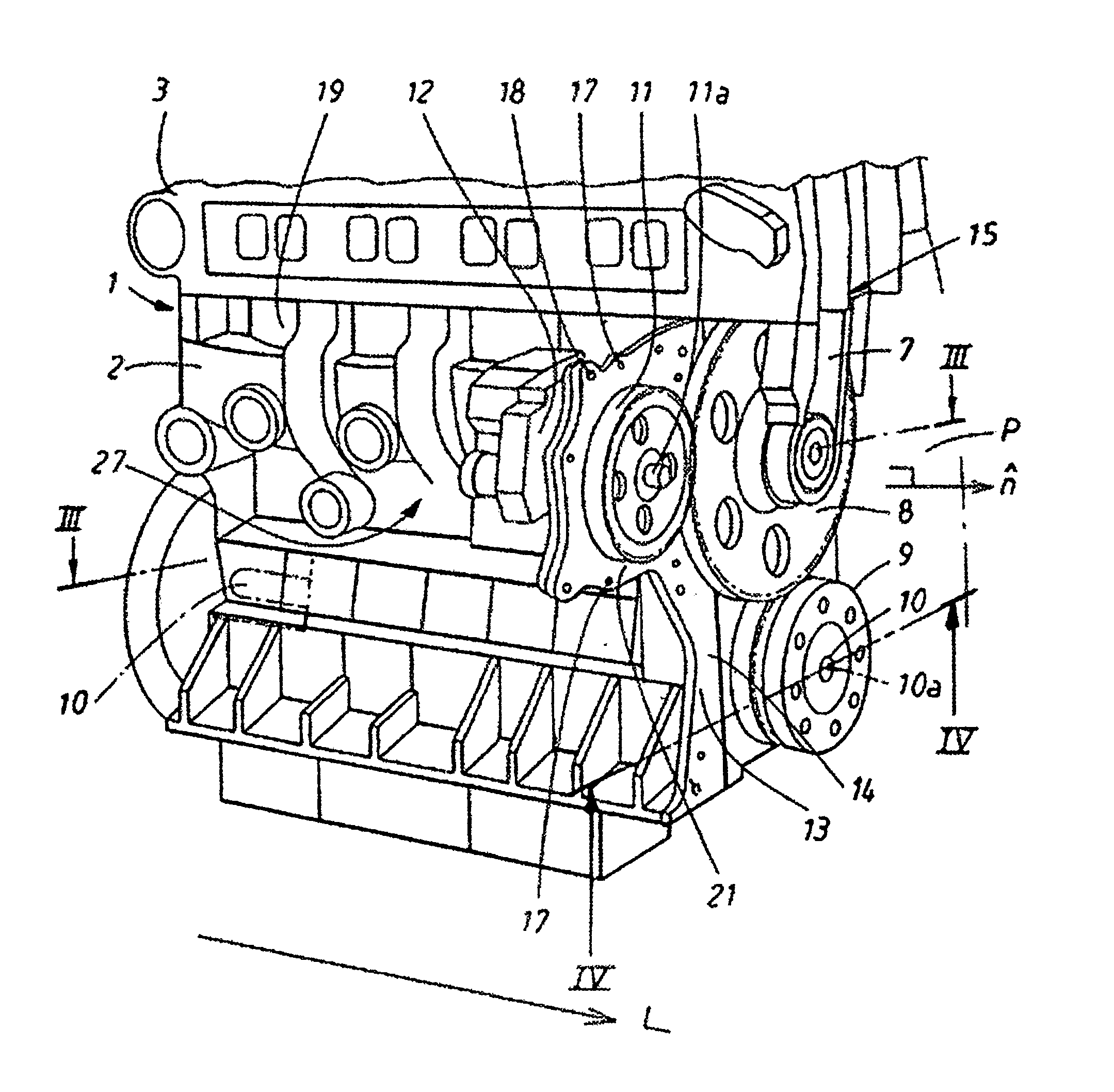
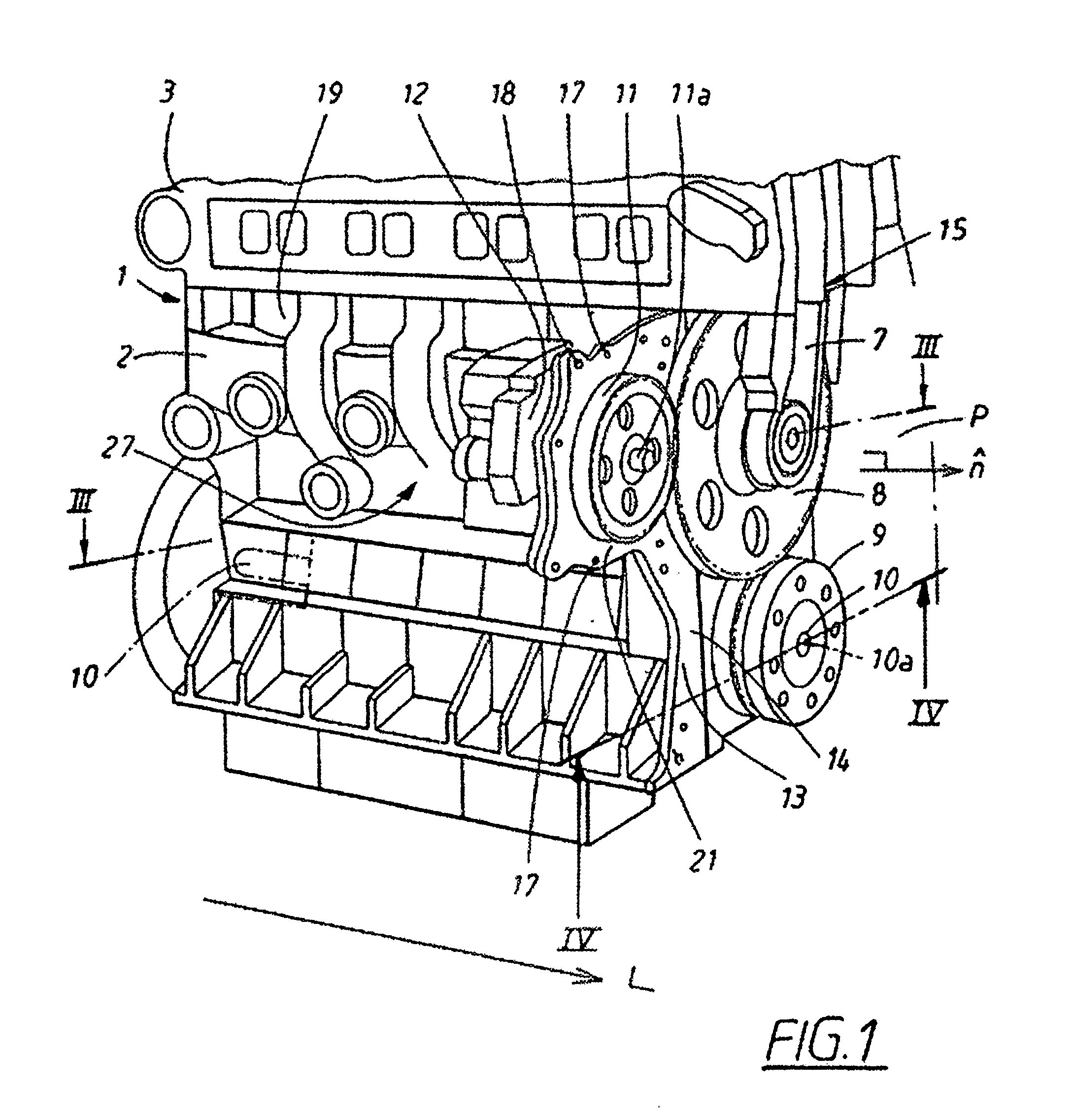
[0022] The internal combustion engine 1 includes an engine block 2 to which is fastened a cylinder head 3. An intermediate wheel 8, which is driven by a drive wheel 9 of the crankshaft 10 drives an auxiliary device 12, for example a fuel pump through, via a power take off arranged as the drive wheel 9 meshed with the intermediate wheel 8, which is in turn meshed with a driven wheel 11 arranged on a drive shaft 11a. Drive wheel 9, intermediate wheel 8 and driven wheel 11 are configured as spur gears.

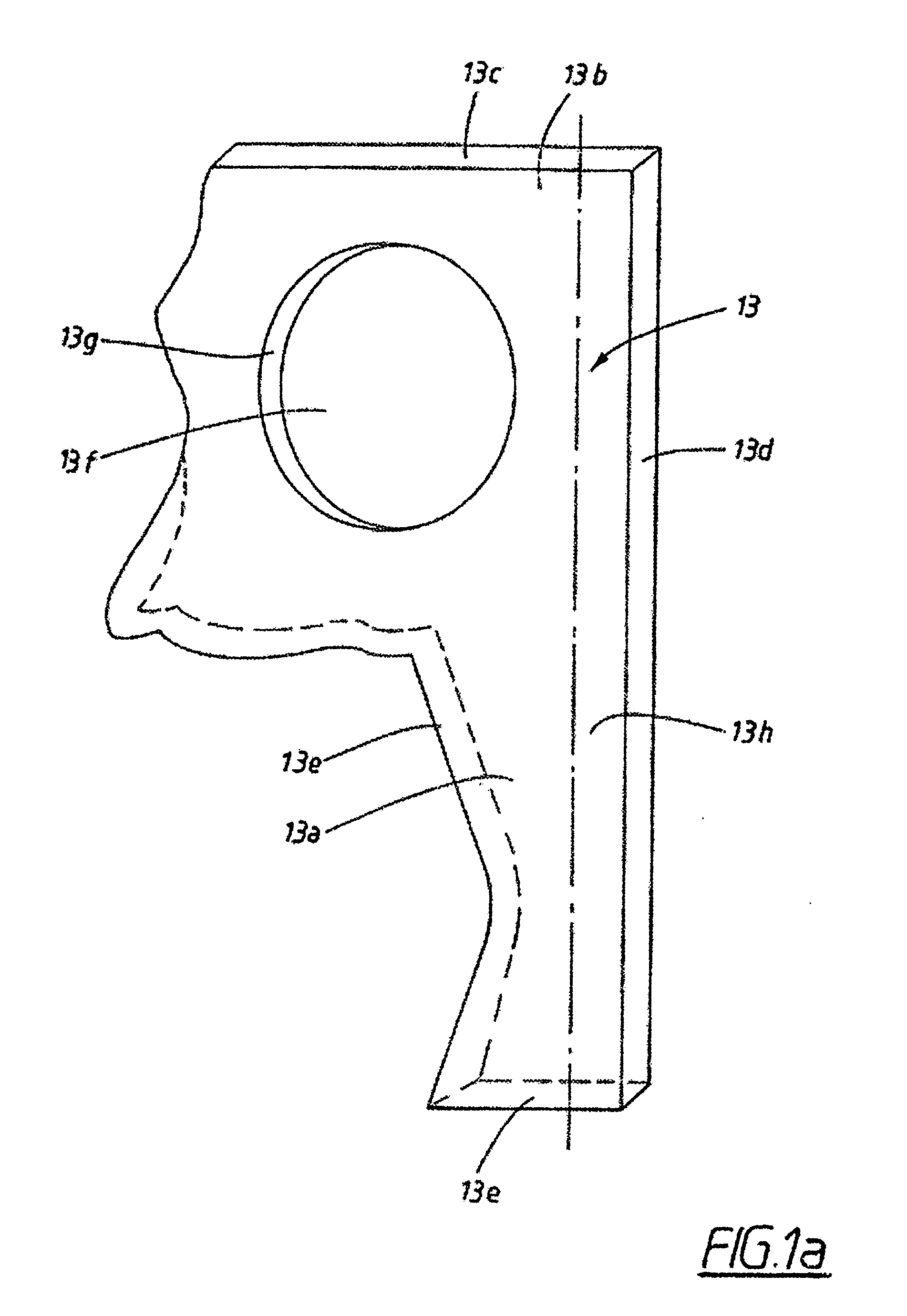
[0023] The auxiliary device 12 is solidly connected to an ear portion formed as an essentially flat rigid plate 13 that is arranged normal to the axle 10a of the crankshaft and is in turn rigidly connected to the engine block 2. The plate 13 is thereby configured as a separate component and is detachably connected to the engine block 2 in a region adjacent the engine block 2.

[0024] The essenti...


PUM


Abstract

An internal combustion engine including an engine block provided with an ear portion arranged to carry an auxiliary device driven by a power take off arranged on a crank shaft mounted in said engine block.

Description

CROSS-REFERENCE TO RELATED APPLICATIONS: [0001] The present application is a continuation patent application of International Application No. PCT / SE2004 / 000913 filed 11 Jun. 2004 which is published in English pursuant to Article 21(2) of the Patent Cooperation Treaty, and which claims priority to European Application No. 03076915-2 filed 19 Jun. 2003. Said applications are expressly incorporated herein by reference in their entireties.TECHNICAL FIELD OF THE INVENTION [0002] The invention relates to an internal combustion engine, and particularly to an internal combustion engine including an engine block provided with an ear portion arranged to carry an auxiliary device. BACKGROUND OF THE INVENTION [0003] In known internal combustion engines, auxiliary devices such as fuel pumps, generators and / or compressors are usually fastened to a mounting flange that is configured integral with the engine block. Such an integral mounting flange is conventionally defined as an ear portion. An ear...

Claims


Application Information

Patent Timeline
Patent Type & Authority Applications(United States)
IPC IPC(8): F16M1/00F02B67/04F02F7/00
CPCF02F7/0073F02B67/04
Inventor PETUTSCHING, WOLFGANGKIRCHWEGER, KARLSTEFANSSON, RICKARDANDERSSON, BERTIL
Owner VOLVO PENTA AB
Why Eureka
Try Eureka