
System and Method for Streaming High Frequency Trace Data Off-Chip

a high frequency trace data and data streaming technology, applied in the field of data processing system and method, can solve the problems of large storage capacity, insufficient internal visibility, limited sampling window size, etc., and achieve the effect of reducing the large amount of high frequency data

Inactive Publication Date: 2008-01-17
IBM CORP
View PDF11 Cites 30 Cited by
  • Summary
  • Abstract
  • Description
  • Claims
  • Application Information

AI Technical Summary

Benefits of technology

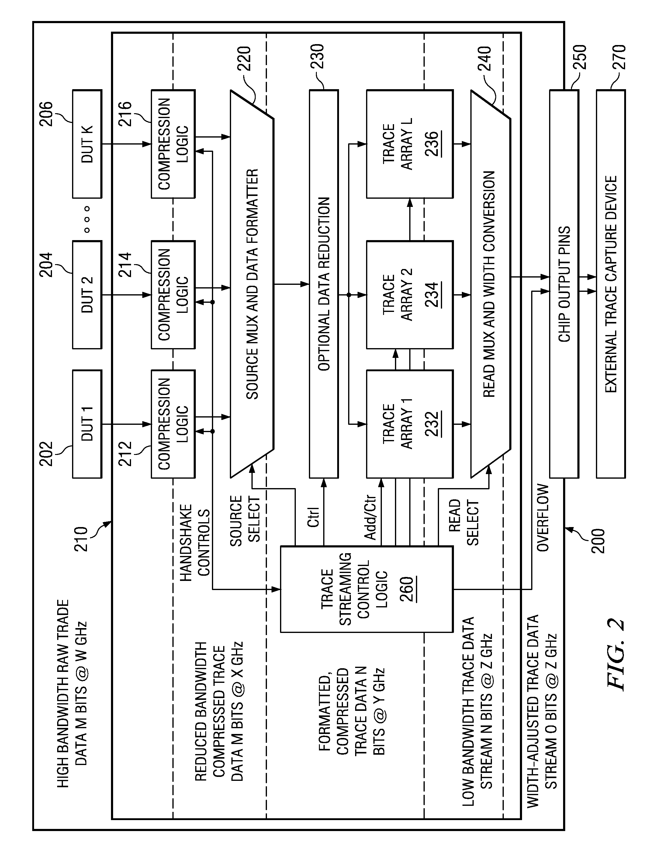
[0010]The exemplary embodiments recognize the disadvantages of the prior art and provide an on-chip trace engine that stores trace data in on-chip trace arrays and routes the trace data to output pins. An external trace capture device captures the trace data. The on-chip trace engine enables the storage and reconstruction of complete traces with the use of lossless compression to reduce the large amounts of high frequency data. The on-chip trace engine streams the trace data through the debug output pins at a slower rate that can be supported by external trace capture device.

Problems solved by technology

A drawback of this architecture is the limited size of the sampling window due to constrained memory and chip input / output (I / O) resources.
Tradeoffs of cost, area, and power consumption may result in a design with relatively small trace arrays, which may not be sufficient for complete internal visibility into the design.
Trace systems that use main memory for trace data storage exhibit significantly larger storage capacity; however, these systems are severely limited by multiple factors.
Another limitation of using main memory storage is the inherent interference experienced when trace data is recorded.
Therefore, to record trace data, the processor must be stalled or the trace engine must steal available bus cycles.
Both may alter the state of the system and, thus, corrupt the device under test (DUT).
Although chip output pins provide a conduit that would appear to solve the capacity problem, systems have not used this option to capture wide busses of at-speed data without discarding data.
Lossless tracing through the chip output pins is not possible without some processing mechanism, because the functions that are being traced typically operate at clock frequencies much higher than can be supported by chip output pins.
These solutions do not provide lossless mechanisms to record and recover the complete trace.
While this expands the ability of a trace array to capture more data over a larger period of time, it is still limited by the compressibility of the trace data and the array capacity when the data is exclusively stored in on-chip arrays.

Method used


Image

  • System and Method for Streaming High Frequency Trace Data Off-Chip
  • System and Method for Streaming High Frequency Trace Data Off-Chip
  • System and Method for Streaming High Frequency Trace Data Off-Chip

Examples


Embodiment Construction

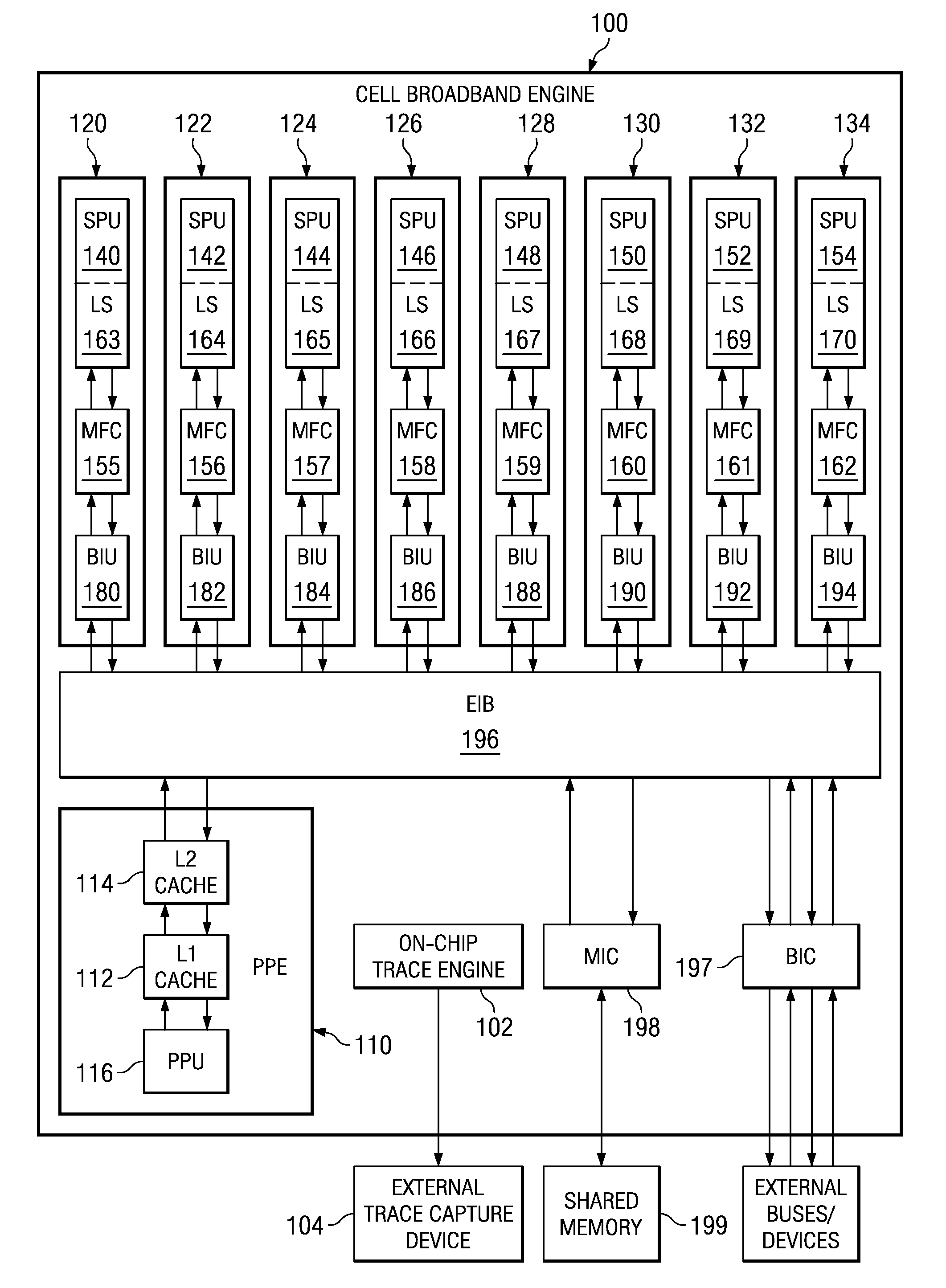
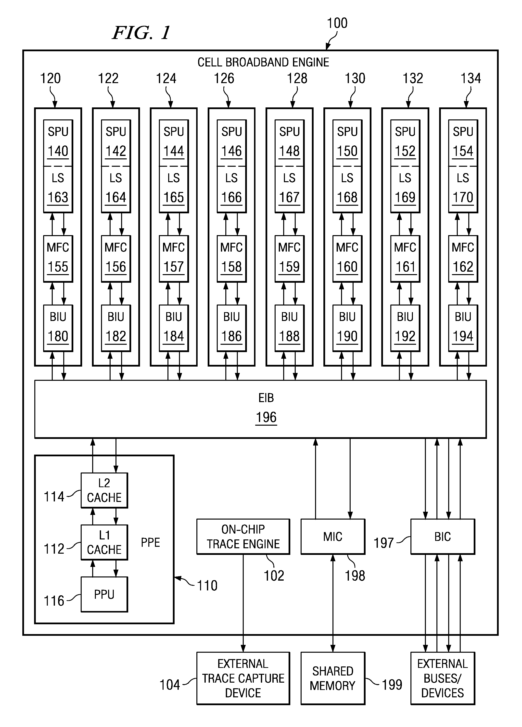
[0031]FIG. 1 is an exemplary block diagram of a data processing system in which aspects of the present invention may be implemented. The exemplary data processing system shown in FIG. 1 is an example of the Cell Broadband Engine (CBE) data processing system. While the CBE will be used in the description of the embodiments of the present invention, the present invention is not limited to such, as will be readily apparent to those of ordinary skill in the art upon reading the following description.

[0032]As shown in FIG. 1, the CBE 100 includes a power processor element (PPE) 110 having a processor (PPU) 116 and its L1 and L2 caches 112 and 114, and multiple synergistic processor elements (SPEs) 120-134 that each has its own synergistic processor unit (SPU) 140-154, memory flow control 155-162, local memory or store (LS) 163-170, and bus interface unit (BIU unit) 180-194 which may be, for example, a combination direct memory access (DMA), memory management unit (MMU), and bus interface...


PUM


Abstract

An on-chip trace engine stores trace data in on-chip trace arrays and routes the trace data to output pins. An external trace capture device captures the trace data. The on-chip trace engine enables the storage and reconstruction of complete traces with the use of lossless compression to reduce the large amounts of high frequency data. The on-chip trace engine streams the trace data through the debug output pins at a slower rate that can be supported by external trace capture device.

Description

BACKGROUND[0001]1. Technical Field[0002]The present application relates generally to an improved data processing system and method. More specifically, the present application is directed to a system and method for streaming high frequency trace data off chip.[0003]2. Description of Related Art[0004]Chip debugging practices rely heavily on capturing signal state transitions in on-chip arrays, referred to as trace arrays, to understand the at-speed behavior of internal processor cores, bus interfaces, and various other components within a chip. Debug information captured in trace arrays can be used to identify logic design errors, timing failures, and performance bottlenecks. Runtime visibility of a large number of signals over an extended period of time enables a quick diagnosis of elusive problems. Successful trace systems provide significant signal visibility without incurring excessive costs of area, power, and complexity.[0005]Typical on-chip trace architectures contain trace arr...

Claims


Application Information

Patent Timeline
Patent Type & Authority Applications(United States)
IPC IPC(8): G06F11/00
CPCG06F11/3636
Inventor ABERNATHY, CHRISTOPHER M.DO, LYDIA M.HALL, RONALD P.KARM, MICHAEL L.
Owner IBM CORP
Learn More