
Dual angle radiation scanning of objects

a radiation scanning and object technology, applied in the field of dual angle radiation scanning of objects, can solve the problems of false positives, unnecessary delays in the processing of many cargo conveyances, luggage,

Active Publication Date: 2008-01-17
VAREX IMAGING CORP
View PDF77 Cites 38 Cited by
  • Summary
  • Abstract
  • Description
  • Claims
  • Application Information

AI Technical Summary

Benefits of technology

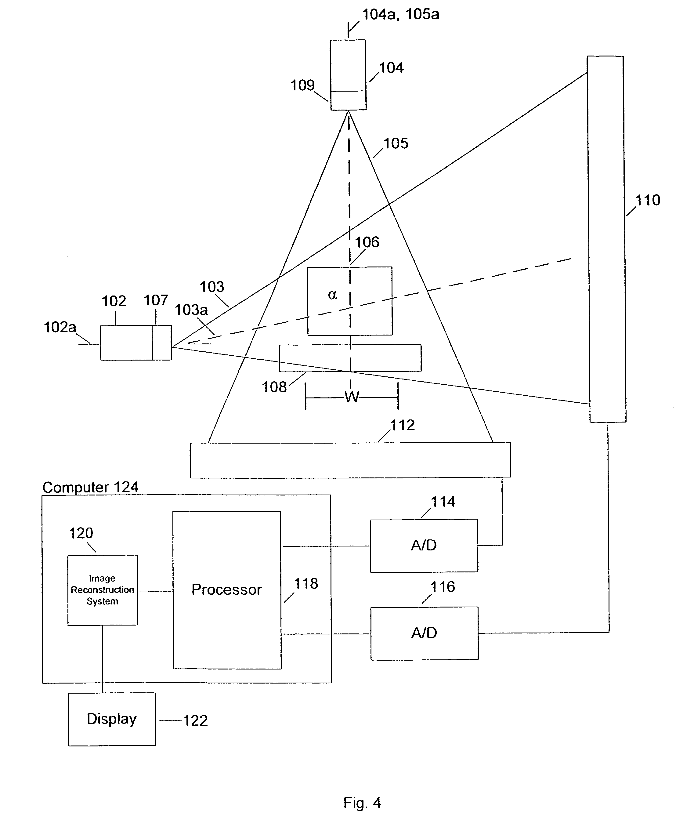
[0019]In accordance with another embodiment of the invention, a system for examining contents of an object is disclosed comprising means for scanning at least a portion of an object at first and second, different angles, means for detecting radiation interacting with the object at the first and second angles, and means for determining whether the object at least potentially comprises high atomic number material, based, at least in part, on the radiation detected at the first and second angles.
[0020]In accordance with another embodiment of the invention

Problems solved by technology

Large regions of moderate and / or low density materials will therefore cause false positives for nuclear / shielding material in X-ray images, that need to be further investigated.
This causes unnecessary delays in processing of many cargo conveyances, luggage, etc.

Method used


Image

  • Dual angle radiation scanning of objects
  • Dual angle radiation scanning of objects
  • Dual angle radiation scanning of objects

Examples


Embodiment Construction

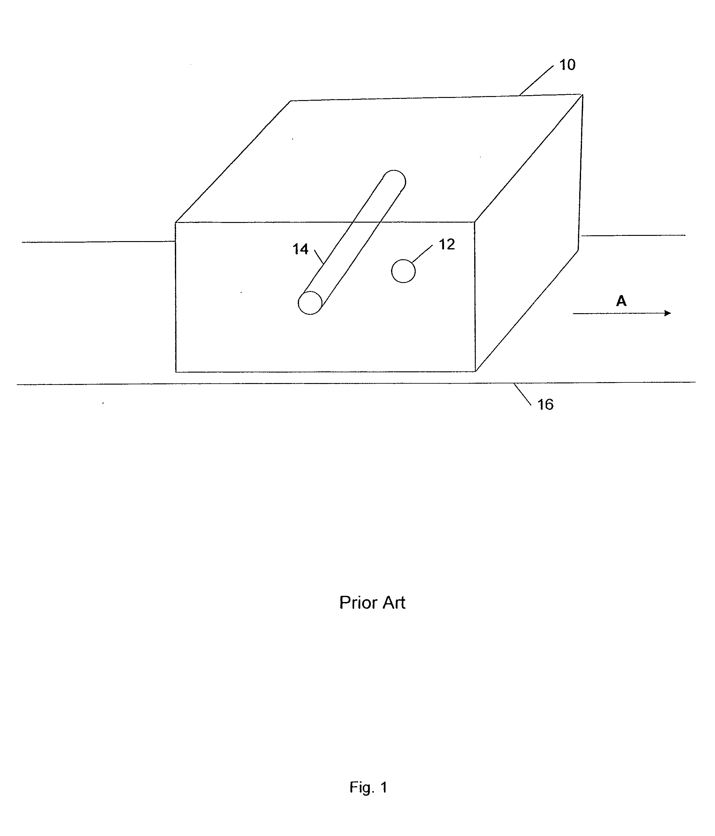
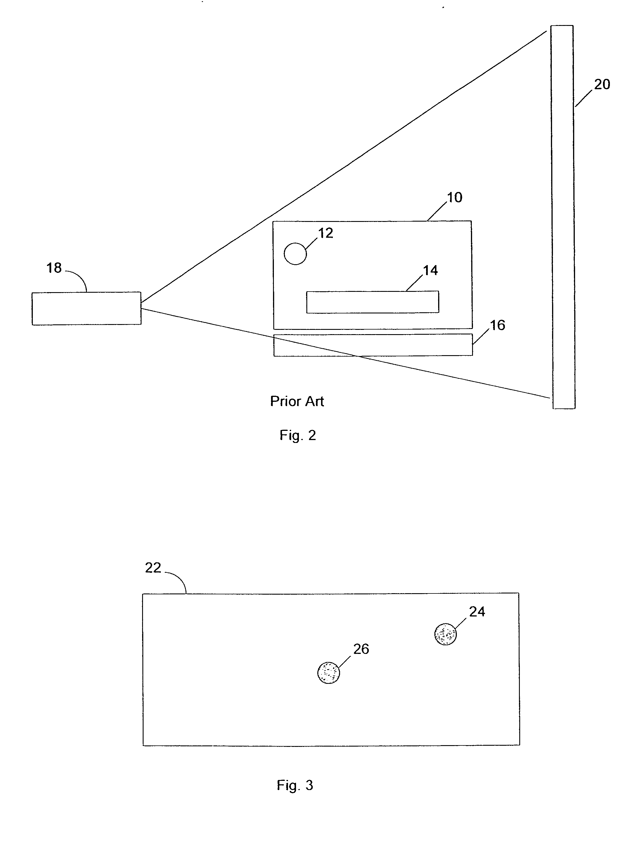
[0034]FIG. 1 is a perspective view of an example of an object 10, such as a rectangular cargo conveyance, containing a sphere 12 of a high density SNM, such as uranium-233 (density of about 20 g / cm3) and a solid pipe 14 of a moderate density material, such as iron (density of about 8 g / cm3), for example, moving through an example of an X-ray scanning system. The object 10 is on a conveyor 16, moving to the right, as indicated by arrow A. FIG. 2 is a front view of the object 10 on the conveyor 16, also showing a radiation source 18 and a detector 20. FIG. 3 is an example of an X-ray image 22 resulting from radiation scanning of the object 10, including the sphere 12 of high density material, indicated by a high density region 24, and the iron pipe 14, indicated by a high density region 26. In this example, the pipe 14 has a length such that the radiation attenuation caused by the pipe is comparable to the attenuation caused by the sphere 12 of uranium. The two regions 24, 26 are ther...


PUM


Abstract

In one example, a method of examining contents of an object is disclosed comprising scanning an object by first and second radiation beams at at least first and second angles, detecting radiation at the first and second angles, and determining whether the object at least potentially comprises high atomic number material, which may be nuclear material or shielding material, based, at least in part, on the detected radiation. In one example, the detected radiation at both angles must be indicative of a region of high atomic number material by the presence of corresponding high density regions, in order for it to be concluded that high atomic number material that may be nuclear material may be present. The determination may be further based on the size of a high density region in one of the images. Systems are also disclosed.

Description

FIELD OF THE INVENTION[0001]Radiation scanning of objects, including large objects such as cargo containers, to identify contraband.BACKGROUND OF THE INVENTION[0002]Radiation is commonly used in the non-invasive inspection of contents of objects, such as luggage, bags, briefcases, cargo containers, and the like, at airports, seaports, and public buildings, for example, to identify hidden contraband. The contraband may include hidden guns, knives, explosive devices, illegal drugs, and weapons of mass destruction, such as a nuclear or a “dirty” radioactive bomb, for example. During radiation scanning, an object is irradiated by a radiation beam. Radiation transmitted through the object, which is attenuated to varying degrees by the contents, dependent on the densities of the materials through which the radiation beam passes, is detected. Higher density materials or regions within the object attenuate radiation more than less dense materials, resulting in darker or lighter regions on a...

Claims


Application Information

Patent Timeline
IPC IPC(8): G01N23/00
CPCG01N23/04G01N2223/639G01N2223/626G01N2223/402
Inventor BJORKHOLM, PAUL
Owner VAREX IMAGING CORP
Learn More