System and method for mounting equipment and structures offshore

a technology for mounting equipment and structures, applied in the direction of floating buildings, bridges, artificial islands, etc., can solve the problems of limiting the possible motion of elements, and achieve the effect of obtaining orientational stability, reducing the risk of elements, and simplifying the design

Active Publication Date: 2008-01-17
THEY JAN
View PDF17 Cites 51 Cited by
  • Summary
  • Abstract
  • Description
  • Claims
  • Application Information

AI Technical Summary

Benefits of technology

[0021]In still another aspect the foundation may float in the water held by partially submerged buoyancy tanks. The mounting system is attached to the floating foundation, allowing the system to be deployed in very deep water. The mounting system reduces the wave induced forces onto the floating foundation. The foundation is located far below the water line, at a depth where the motion of the waves is low. The floating stability of the foundation is provided by additional buoyant structures mounted to the foundation, so that the buoyancy volume of the mounting system (connecting elements and carrier) can remain below the waterline. The additional buoyant bodies can be mounted flexible to the foundation, thereby largely avoiding transfer of wave induced forces from the buoyant bodies to the foundation. Buoyant bodies may also be mounted rigidly to the foundation simplifying the design.
[0022]In a further example the system may also be used to carry a bridge. Especially in deep waters like in a fjord the disclosed mounting system can provide a low cost and wave resistant grounding for a bridge, e.g. carrying the mast of a suspension bridge. The ropes, which hold the bridge, usually only carry the bridge's weight, while the bridge obtains its orientational stability from mountings at the end of the bridge. Therefore the suspension bridge is not sensitive to small motions of the mast, allowing it to be mounted to the disclosed mounting system.
[0023]For static reasons it is advantageous to locate parts of the buoyant volume close to where the connecting elements are attached to the carrier. That way the excess buoyancy can by transferred directly to the foundation without putting load onto other parts of the devi

Problems solved by technology

The connecting elements limit possible motio

Method used


Image

  • System and method for mounting equipment and structures offshore
  • System and method for mounting equipment and structures offshore
  • System and method for mounting equipment and structures offshore

Examples


Embodiment Construction

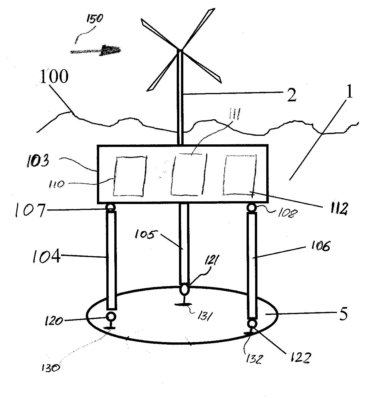
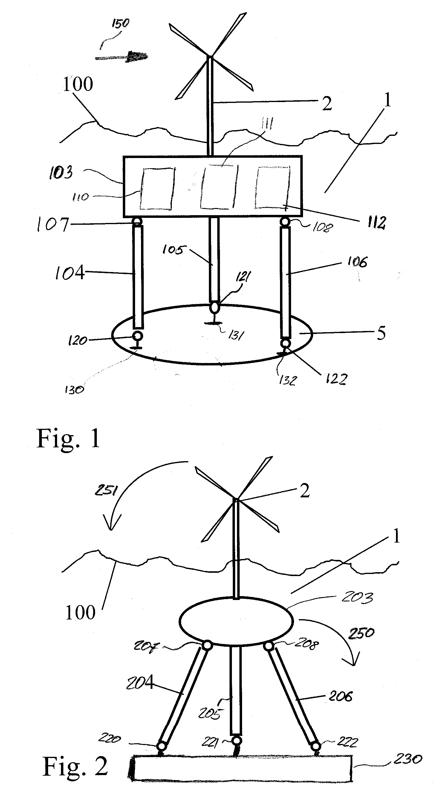
[0036]Referring to FIG. 1 a schematic drawing of an exemplary mounting system 1 in which the principles of the present invention may be advantageously practiced is illustrated generally. As illustrated, the exemplary system carries structure 2, which is illustrated as a wind-electric generator. Structure 2 is securely attached to carrier 103. Carrier 103 is attached to connecting elements 104,105,106. Connecting elements 104,105,106 are attached to foundation 5, which here is seabed. Any other stable structure may be used as a foundation. Suitable alternative foundation structures are discussed below.

[0037]The connecting elements 104,105,106 are joint swiveling to the carrier 103 and the foundation 5, preferably with carrier joints 107,108 and anchor joints 120,121,122. Connecting elements 104,105,106 limit motion of carrier 103 along each connecting elements longitudinal axis. Depending on to the number and orientation of the connecting elements 104,105,106 the motion in other dire...


PUM


Abstract

A mounting system is disclosed for mounting structures and equipment such as wind-electric generators on water. The structure is attached to a carrier, which is attached to a foundation through connecting elements. Buoyancy tanks or the inherent buoyancy of the carrier or the connecting elements are used to maintain a stable position of the carrier in the water. Utilizing connecting elements that transfer pushing and pulling force undesirable movements of the carrier are suppressed while requiring only moderate forces on the foundation.

Description

CLAIM FOR PRIORITY[0001]This application claims priority to German application number DE102006033215.6 which was filed in the German language on Jul. 13th, 2006 and which is hereby incorporated by reference.TECHNICAL FIELD[0002]The present invention generally relates to a system and method for mounting equipment and structures offshore, and more particularly, to a system and method for mounting high rising equipment and structures on a floating carrier which is attached to a foundation through connecting elements.BACKGROUND OF THE INVENTION[0003]Wind-electric generators provide a clean and renewable source of electric energy. Mounting wind-electric generators offshore is particularly attractive, as winds offshore are often stronger and steadier than on land. Further, offshore structures often face less resistance by neighbors afraid of noise pollution or the appearance of high rising structures in general. However, wind-electric generators experience high forces acting on their roto...

Claims


Application Information

Patent Timeline
IPC IPC(8): E02D5/74
CPCB63B1/04B63B1/107B63B21/50B63B21/502B63B35/44B63B2001/044Y02E10/727E01D15/14E01D19/02E02B2017/0091F03D11/045F05B2240/93B63B2035/446F03D13/22F03D13/25Y02E10/72
Inventor THEY, JAN
Owner THEY JAN
Why Eureka
Try Eureka