
Electrical fire prevention from over-temperature conditions

Inactive Publication Date: 2008-01-17
KOPELMAN ROBERT Z
View PDF14 Cites 39 Cited by
  • Summary
  • Abstract
  • Description
  • Claims
  • Application Information

AI Technical Summary

Benefits of technology

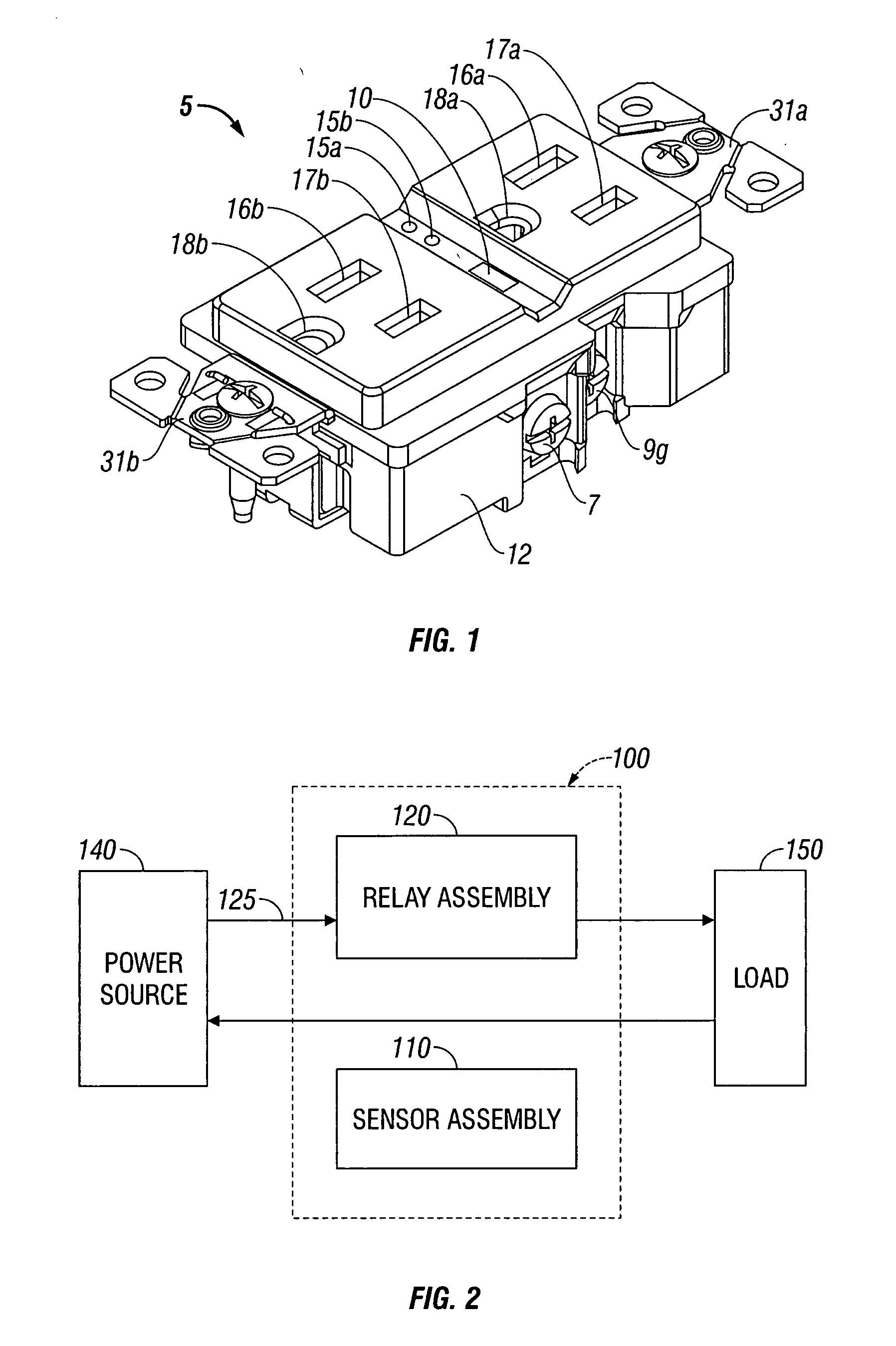
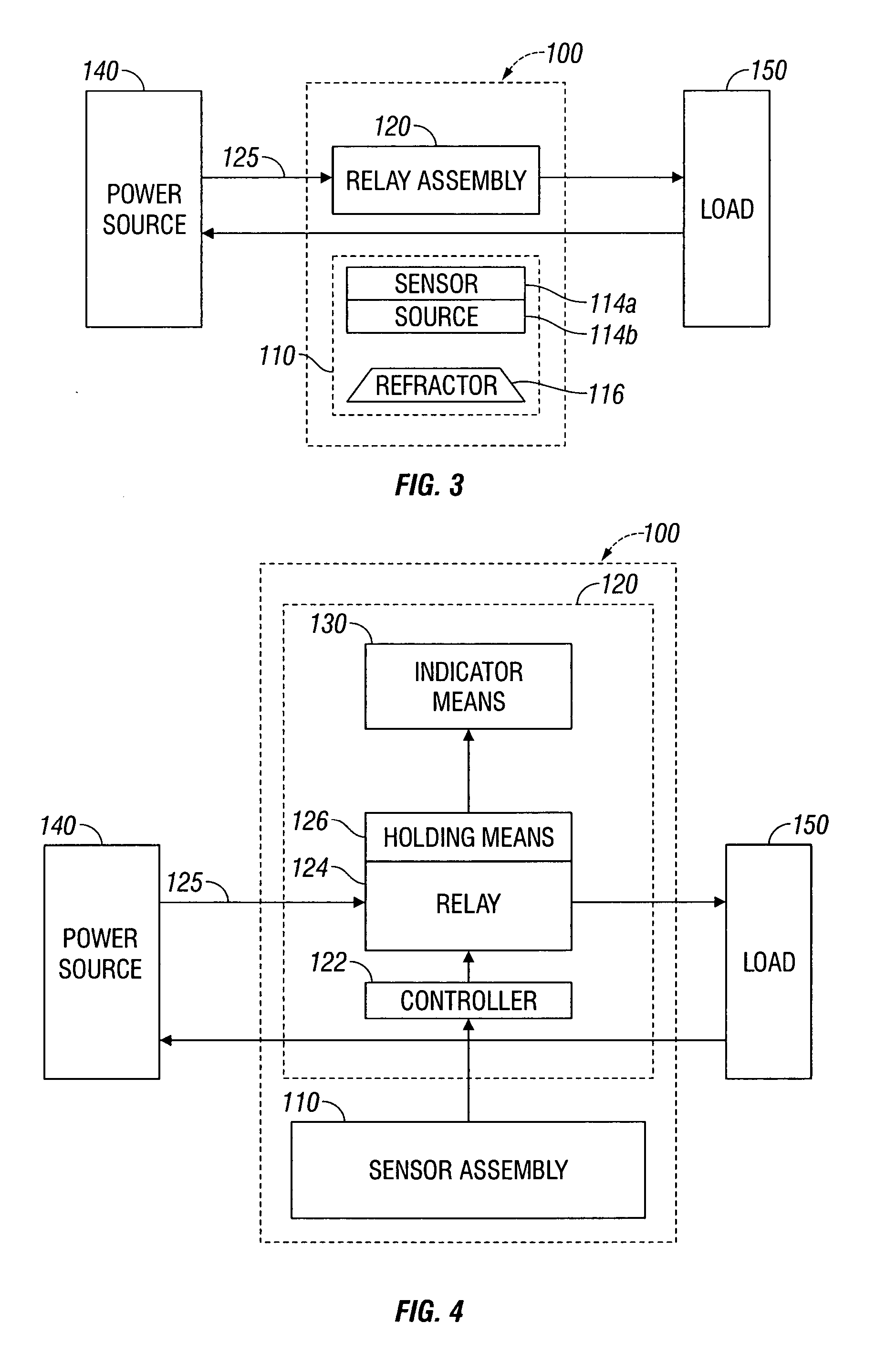
[0011] The present disclosure further relates to a heat sensing circuit interrupter configured to enable a load to be selectively connected to or disconnected from a power source in accordance with a level of a sensed temperature. The circuit interrupter includes a relay assembly operable between a closed state when the sensed temperature is below a predetermined limit temperature, thereby enabling the coupling of the load to the power source, and an open state when the sensed temperature is above the predetermined limit temperature, thereby electrically disconnecting the load from the power source. The circuit interrupter further includes a sensor assembly including a light source operatively associated with a light sensor. The light sensor is configured to be sensitive to specific levels of the sensed temperature and the light source is configured to emit light along a plurality of optical paths at any one of a plurality of wavelengths sensitive to temperature. The light sensor is further configured to sense temperature at any one of a plurality of operating points on the electrical device and trigger the relay assembly between the closed state and the open state.

Problems solved by technology

An over-temperature event of these devices may require manual resetting to again enable power to be coupled to a load.
However, with reference to conventional devices, the temperature controlled relay may only be electrically and / or mechanically coupled to a ‘hot’ or power sourcing conductor.
Accordingly, there is a possibility that heat generated by other conductors (or related structures and current carrying means) may not be appropriately sensed due to their physical location and possibly due to the nature of the electrical connections of the temperature controlled relay.
Therefore, when considering conventional circuit interrupters, there is currently lacking a simple and cost effective arrangement to thermally sense and monitor the heat produced by any of a plurality of current carrying means (e.g., conductors, female prongs, terminal screws, etc.) to determine if the temperature of any one of said means has risen above a predetermined limit.
For example, an elevated temperature level may be caused by a poorly formed resistive contact and / or an excessive current flow of a neutral conductor or a ground, or even a high resistance grounding condition.

Method used


Image

  • Electrical fire prevention from over-temperature conditions
  • Electrical fire prevention from over-temperature conditions
  • Electrical fire prevention from over-temperature conditions

Examples


Embodiment Construction

[0017] Particular embodiments of the present disclosure are described hereinbelow with reference to the accompanying drawings. In the following description, well-known functions or constructions are not described in detail to avoid obscuring the present disclosure in unnecessary detail.

[0018] The present disclosure provides for a temperature sensitive and controlled circuit interrupting device configured to disconnect a load from a power source with the occurrence of an over-temperature event at any one or more points along a circuit associated with the delivery of power from the power source to the load.

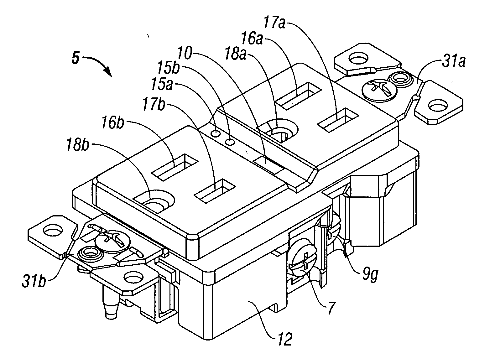
[0019] Referring to FIG. 1, an electrical receptacle 5 including an outlet is shown. The circuit interrupting device of the present disclosure is configured to sense the operating temperature of electrical devices and / or circuits such as, for example, electrical receptacle 5. More particularly, the circuit interrupting device of the present disclosure is configured to sense the op...


PUM


Abstract

An electrical device including a heat sensing circuit interrupter to enable a load to be selectively coupled to or disconnected from a power source in accordance with a level of a sensed temperature includes a relay assembly operable between a closed state when the sensed temperature is below a predetermined limit temperature, thereby enabling the coupling of the load to the power source, and an open state when the sensed temperature is above the predetermined limit temperature, thereby electrically disconnecting the load from the power source. The device further includes a sensor assembly including a light source operatively associated with a light sensor. The light sensor is configured to be sensitive to specific levels of the sensed temperature and the light source is configured to emit light along a plurality of optical paths at any one of a plurality of wavelengths sensitive to temperature. The light sensor is further configured to sense temperature at any one of a plurality of operating points on the electrical device and trigger the relay assembly between the closed state and the open state.

Description

[0001] This application claims priority from U.S. Provisional Patent Application Ser. No. 60 / 786,725 filed on Apr. 17, 2006 entitled “Electrical Fire Prevention from Over-temperature Conditions,” the entire contents of which are incorporated herein by reference. [0002] This application also claims priority from U.S. Provisional Patent Application Ser. No. 60 / 786,726 filed on Mar. 28, 2006 entitled “Prevention of High Resistance Electrical Connections,” the entire contents of which are incorporated herein by reference.BACKGROUND [0003] 1. Technical Field [0004] The present disclosure relates to an electrical safety device. More particularly, the invention relates to a temperature sensitive and controlled circuit interrupting device that is arranged to electrically disconnect a load from a power source with the occurrence of an over-temperature event associated with the delivery of power from the power source to the load. [0005] 2. Background of Related Art [0006] The device of the pr...

Claims


Application Information

Patent Timeline
IPC IPC(8): H02H5/04
CPCG01J5/58G01K3/005H01H37/74H01R25/006H01R13/6683H01R13/70H01R13/717H01R13/665H02H5/045
Inventor KOPELMAN, ROBERT Z.
Owner KOPELMAN ROBERT Z
Learn More