
Liquid crystal device

Inactive Publication Date: 2008-01-17
CITIZEN WATCH CO LTD
View PDF2 Cites 1 Cited by
  • Summary
  • Abstract
  • Description
  • Claims
  • Application Information

AI Technical Summary

Benefits of technology

[0015]It is an object of the present invention to provide a liquid crystal device wherein provisions are made to reduce the occurrence of light leakage and discrimination and improve the display image quality, while also improving the production yield.
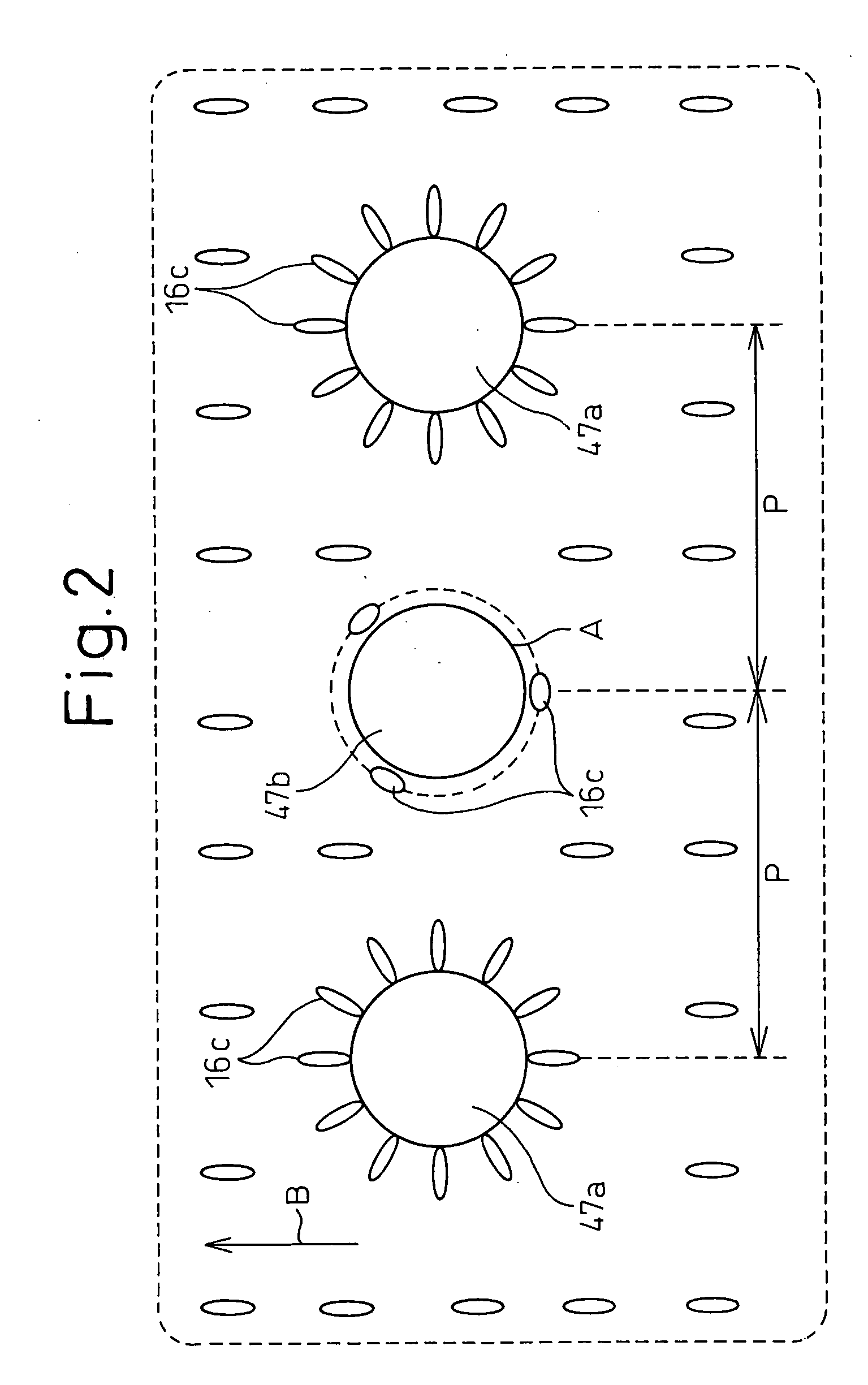
[0023]In the present invention, the coated spacers (or the first spacers having a strong perpendicular alignment function) and the uncoated spacers (or the second spacers having a weak perpendicular alignment function) are mixed together such that the coated spacers serve to reduce the rate of occurrence of light leakage around the spacer surfaces while the presence of the uncoated spacers serves to reduce the rate of occurrence of discrimination. Accordingly, the liquid crystal device according to the present invention achieves an improvement in image quality or display quality. Furthermore, the liquid crystal device according to the present invention can be produced with high production yield and achieves a reduction in production cost.

Problems solved by technology

However, the liquid crystal device 20 using the spacers 17 has the problem that bright spots appear around the spacers.
However, it was found that thin line-like light leakage occurs.
It is speculated that this behavior of the liquid crystal molecules 16c results in the occurrence of thin line-like light leakage.
Occurrence of such discrimination impairs the display image quality of the liquid crystal display device and decreases the production yield.

Method used


Image

  • Liquid crystal device
  • Liquid crystal device
  • Liquid crystal device

Examples


Embodiment Construction

[0032]A liquid crystal device according to the present invention will be described below with reference to the drawings. It should be understood, however, that the invention is not limited to the embodiment illustrated in the drawings.

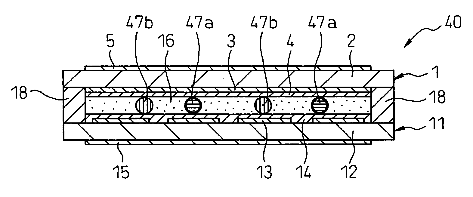
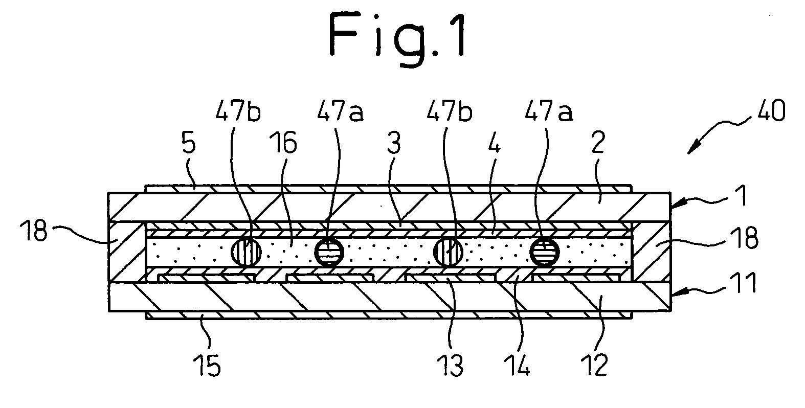
[0033]FIG. 1 is a cross-sectional view showing an essential portion of the liquid crystal device according to the present invention.

[0034]As shown in FIG. 1, the liquid crystal device 40 includes a pair of transparent substrates, i.e., a top substrate 1 and a bottom substrate 11, arranged opposite each other. The top substrate 1 comprises a top transparent substrate 2 formed from transparent glass, a top transparent electrode 3 formed from an ITO (Indium Tin Oxide) film deposited on the lower surface thereof, and a top alignment film 4 formed from a polyimide resin deposited over the top transparent electrode 3. Likewise, the bottom substrate 11 comprises a bottom transparent substrate 12 formed from transparent glass, a bottom transparent electrode 13...


PUM


Abstract

An object of the present invention is to provide a liquid crystal device wherein provisions are made to reduce the occurrence of light leakage and discrimination. The liquid crystal device comprises a pair of opposing substrates, a liquid crystal provided between the pair of opposing substrates, and spacers for maintaining a gap between the pair of opposing substrates, wherein the spacers include a mixture of coated spacers, each coated with an alignment material for giving liquid crystal molecules forming the liquid crystal a tendency to align in a particular direction around the surface of the spacer, and uncoated spacers not coated with an alignment material.

Description

[0001]Applicant claims the right to priority based on Japanese Patent Application No. 2004-101652, filed on Mar. 31, 2004.TECHNICAL FIELD[0002]The present invention relates to a liquid crystal device and, more particularly, to a liquid crystal device having prescribed spacers.BACKGROUND ART[0003]Generally, a liquid crystal display device comprises a pair of transparent substrates arranged opposite each other on top and bottom and each having a transparent electrode and an alignment film, and a liquid crystal filled between the top and bottom substrates. Spacers are inserted between the pair of substrates to provide a prescribed gap therebetween.[0004]FIG. 5 shows a cross-sectional view of a prior art liquid crystal device.[0005]As shown in FIG. 5, the liquid crystal device 20 includes a pair of transparent substrates, i.e., a top substrate 1 and a bottom substrate 11. The top substrate 1 comprises a top transparent substrate 2, a top transparent electrode 3 formed on the lower surfa...

Claims


Application Information

Patent Timeline
IPC IPC(8): G02F1/1339
CPCG02F1/1337G02F1/13392G02F1/133753
Inventor TSUKADA, HIROSHIKURIHARA, MAKOTOCHIBA, JUN
Owner CITIZEN WATCH CO LTD
Learn More