
Fuel Cell System and Fuel Gas Control Method

a fuel cell and gas control technology, applied in the field of fuel cell systems, can solve the problems of increasing the concentration of nitrogen in fuel, lowering the power generation performance of the fuel cell, and not being able to discharge enough nitrogen, etc., to achieve accurate nitrogen concentration estimation, reduce the effect of fuel economy caused by unnecessarily discharging hydrogen, and accurate nitrogen concentration estimation

Inactive Publication Date: 2008-01-10
TOYOTA JIDOSHA KK
View PDF5 Cites 26 Cited by
  • Summary
  • Abstract
  • Description
  • Claims
  • Application Information

AI Technical Summary

Benefits of technology

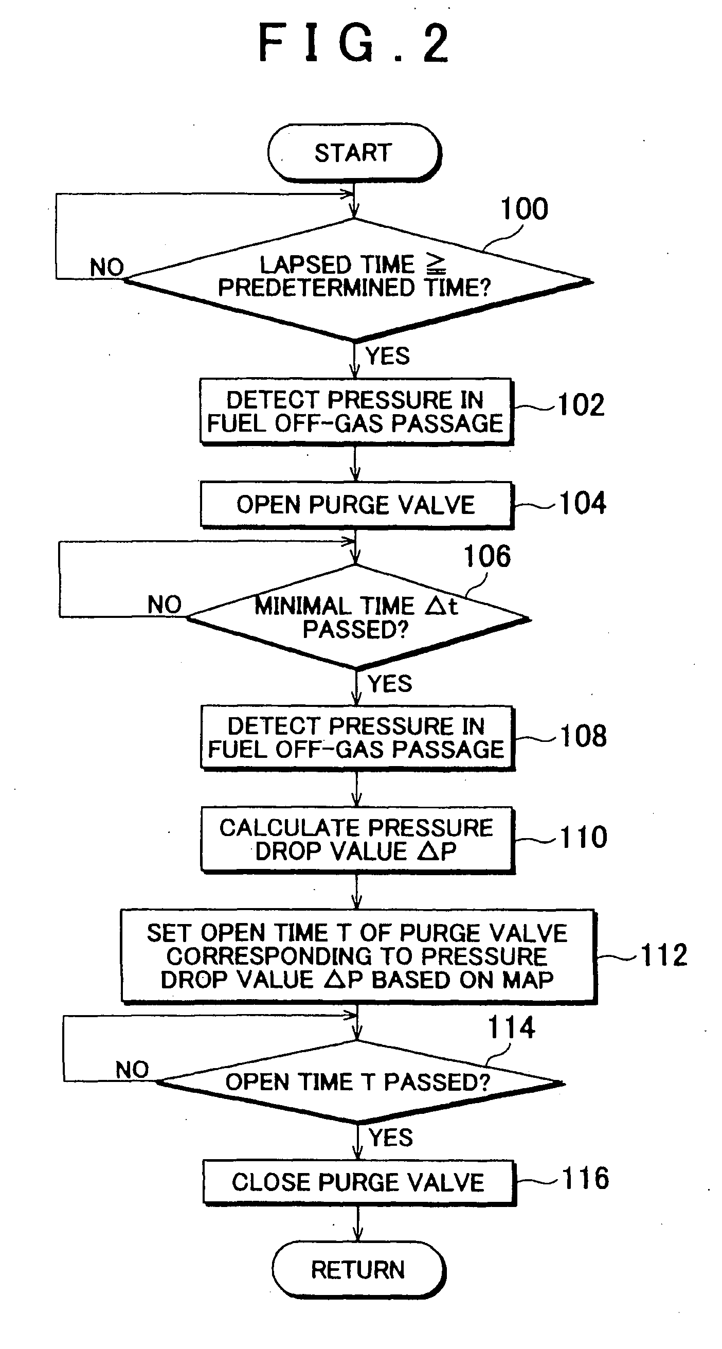
[0011]According to the first aspect, the amount of discharged fuel off-gas discharged from the fuel off-gas passage to outside is controlled depending on the nitrogen concentration of the fuel gas in the fuel cell, thus assuring an optimized amount of discharged fuel off-gas. Consequently, a decrease in fuel economy due to unnecessarily discharging hydrogen can be suppressed when restoring the hydrogen concentration by discharging fuel off-gas.
[0012]In the first aspect, the nitrogen concentration estimation mechanism can estimate the nitrogen concentration from a physical quantity related to the fuel off-gas detected in the fuel off-gas passage. In this case, the ultimate concentration of the nitrogen concentration, which varies depending on the position in the fuel cell, is reflected in the physical quantity related to fuel off-gas. Therefore, estimating the nitrogen concentration from the physical quantity detected in the fuel off-gas passage assures an accurate estimation of the nitrogen concentration of the fuel gas in the fuel cell.
[0013]In an aspect related to the first aspect, the nitrogen concentration estimation mechanism can estimate the nitrogen concentration from a rate of pressure drop in the fuel off-gas passage during discharge of the fuel off-gas by the discharging mechanism. In this case, the rate of pressure drop in the fuel off-gas passage during the discharge of fuel off-gas corresponds to the nitrogen concentration. Therefore, estimating the nitrogen concentration from the rate of pressure drop assures an accurate estimation of the nitrogen concentration of the fuel gas in the fuel cell. Furthermore, the nitrogen concentration can also be estimated from the hydrogen concentration. However, the pressure sensor required for measuring the rate of pressure drop excels over a gas concentration sensor in terms of response. Therefore, according to the invention, the amount of discharged fuel off-gas can be accurately controlled as soon as the nitrogen concentration changes, as compared to using a detection value of the gas concentration sensor.
[0014]In the first aspect and a related aspect, the discharge amount control mechanism can decrease the amount of discharged fuel off-gas in proportion to an increase in the nitrogen concentration when the discharging mechanism is operated while the operation of the fuel cell is stopped. In this case, discharging the fuel off-gas to decrease a hydrogen pressure in the anode is effective for suppressing the permeation of hydrogen to the cathode while the operation of the fuel cell is stopped. However, decreasing the amount of discharged fuel off-gas as the nitrogen concentration of the fuel gas increases prevents the unnecessary discharge of hydrogen when the hydrogen pressure in the anode is small to suppress a decrease in fuel economy.
[0015]In the first aspect and a related aspect, the fuel off-gas passage can be connected to a fuel gas passage, which is a passage for supplying the fuel gas to the fuel cell. In this case, a fuel gas circulation system is constructed when the fuel off-gas passage is connected to the fuel gas passage, and nitrogen accumulates in the circulation system. However, the hydrogen concentration is restored by discharging the fuel off-gas outside the circulation system. Moreover, the discharged amount is controlled in accordance with the nitrogen concentration of the fuel gas; therefore, a decrease in fuel economy due to unnecessarily discharging hydrogen can be suppressed.
[0016]In the first aspect and a related aspect, the discharge amount control mechanism can set an open time of a purge valve for discharging fuel off-gas to outside longer in proportion to an increase in the nitrogen concentration of the fuel gas in the fuel cell.

Problems solved by technology

However, the main component of the oxidation gas is inert nitrogen, which builds up in the fuel gas circulation system, thus gradually increasing the concentration of nitrogen in the fuel gas supplied to the fuel cell.
This increase in the nitrogen concentration of fuel gas also suggests a decrease in the hydrogen concentration, which may lower the power generation performance of the fuel cell.
However, the open time of the valve is fixed in the above art, and therefore, a sufficient amount of nitrogen may not be discharged depending on the state of accumulated nitrogen in the circulation system.
Thus, the hydrogen concentration may not adequately recover.
By leaving the valve open for a fixed period, as in the above art, more hydrogen than necessary may be discharged while the hydrogen concentration is restored, which may also lower fuel economy.

Method used


Image

  • Fuel Cell System and Fuel Gas Control Method
  • Fuel Cell System and Fuel Gas Control Method
  • Fuel Cell System and Fuel Gas Control Method

Examples


Embodiment Construction

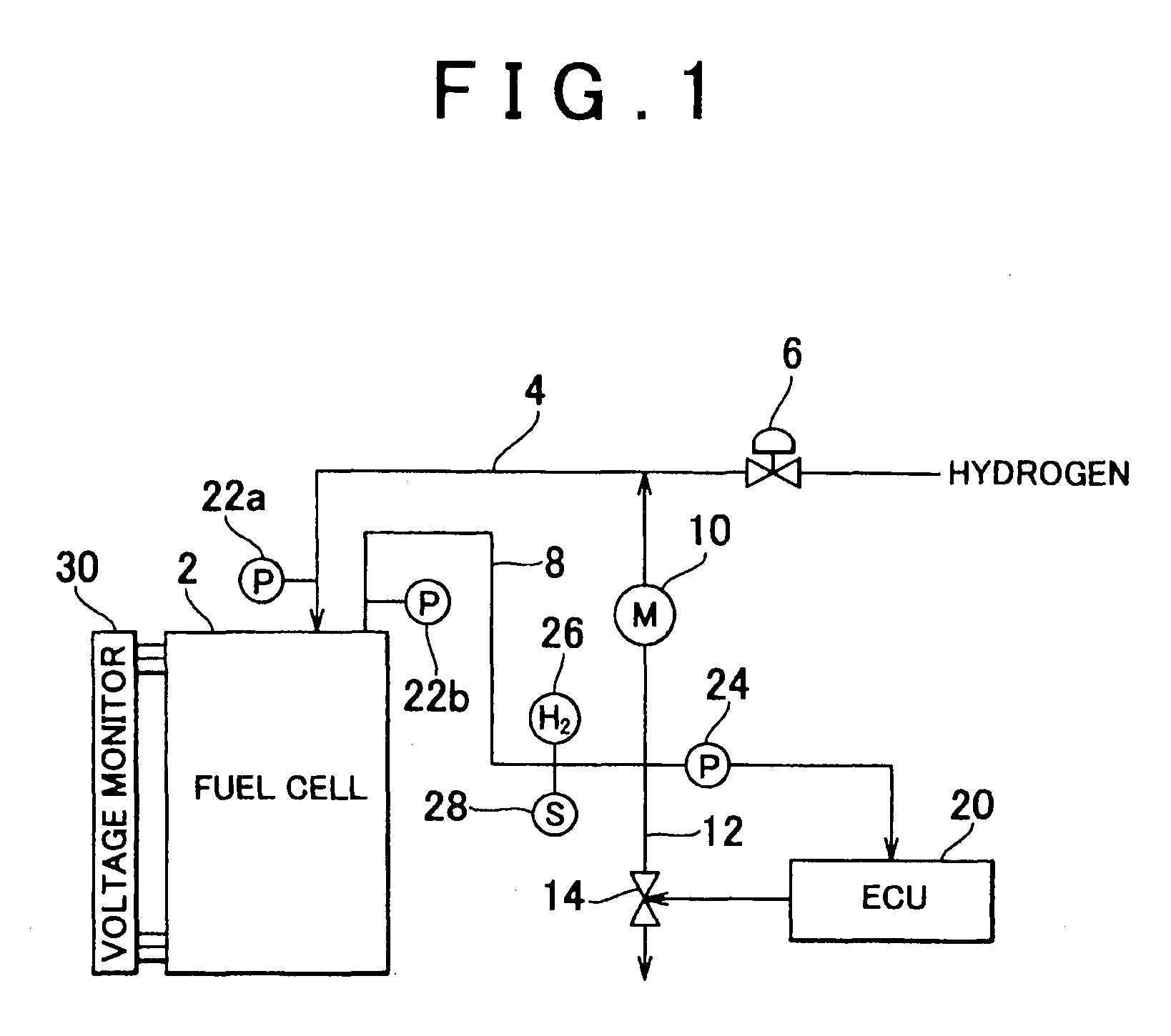
[0027]Hereinafter, an embodiment of the invention will be described with reference to FIGS. 1 to 3.

[0028]A fuel cell system according to the invention may, for example, be applied to other automotive fuel cell systems mounted in vehicles; however, it can also be applied to fuel cell systems for other purposes.

Description Of Fuel Cell System Structure

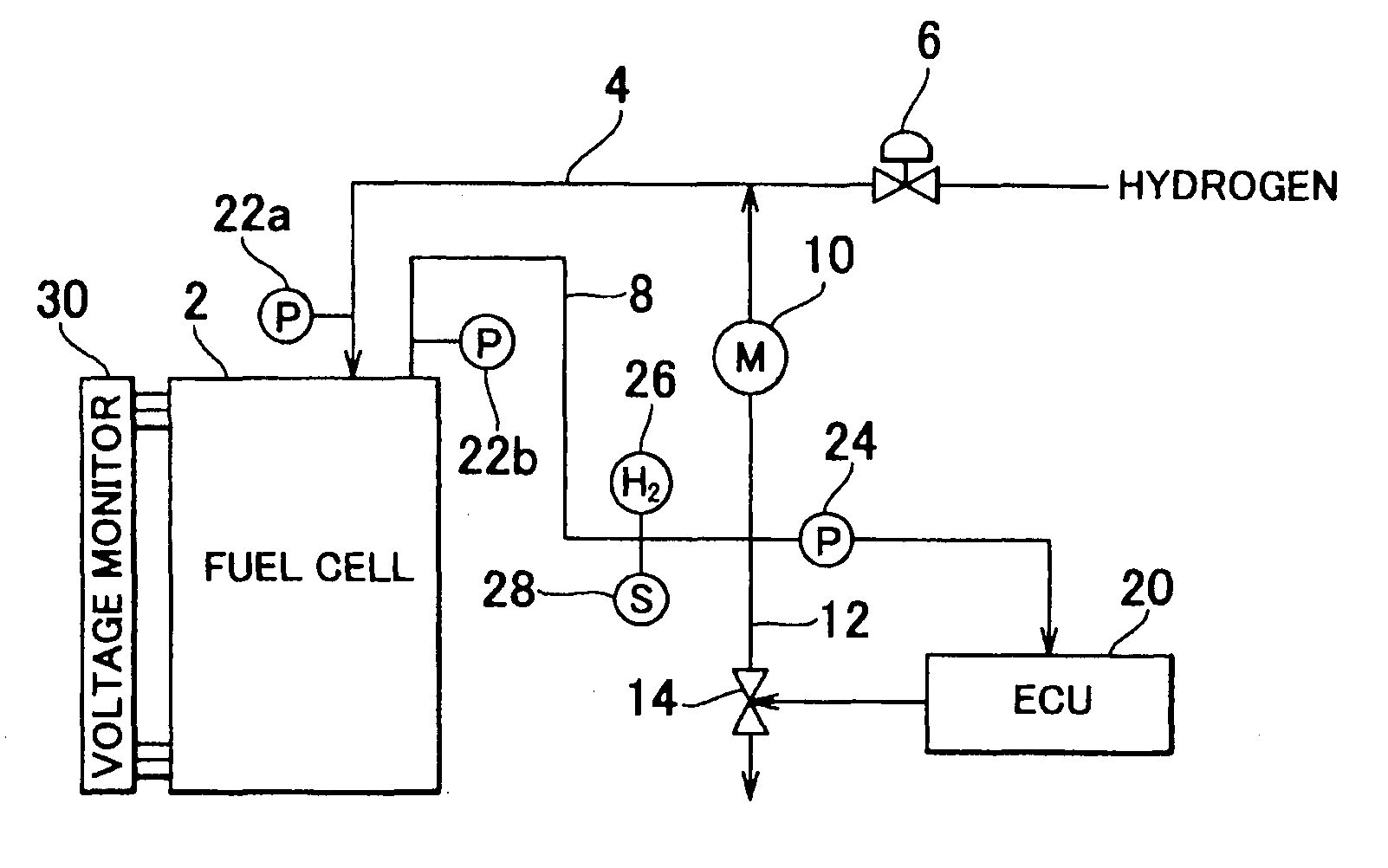
[0029]FIG. 1 is a drawing showing a schematic structure of a fuel cell system serving as a first embodiment of the invention. As shown in the figure, the fuel cell system has a fuel cell 2 serving as an electric power supply mechanism. The fuel cell 2 is structured with an electrolyte membrane permeable to hydrogen ions sandwiched between an anode and a cathode, which are catalytic electrodes (the electrolyte membrane, anode, and cathode are omitted in the figure). Electricity is generated by supplying fuel gas including hydrogen to the anode, and supplying oxidation gas including oxygen from the air or the like to the cathode. A fuel ga...


PUM


Abstract

A nitrogen concentration of fuel gas is estimated, and an amount of discharged fuel off-gas that is discharged from a fuel off-gas passage to outside by a discharging mechanism is controlled depending on the estimated nitrogen concentration. The nitrogen concentration, for example, can be estimated from a rate of pressure drop in the fuel off-gas passage during the discharge of fuel off-gas.

Description

BACKGROUND OF THE INVENTION[0001]1. Field of the Invention[0002]The invention relates to a fuel cell system, and in particular, relates to art for controlling an amount of fuel off-gas discharged from a fuel cell system to outside.[0003]2. Description of the Related Art[0004]A fuel cell has a structure in which an anode and a cathode are arranged with an electrolyte membrane therebetween. An electrochemical reaction occurs when fuel gas including hydrogen contacts the anode, and oxidation gas including oxygen from air or the like contacts the cathode, thus generating an electromotive force. For a fuel cell system that obtains electric power using such a fuel cell, eliminating excessive consumption of hydrogen fuel is important from the standpoint of energy conservation. To this end, a fuel cell system such as that disclosed in, for example, Japanese Patent Application Publication No. JP-A-2002-289237, circulates off-gas of fuel gas used by the fuel cell through the fuel cell again i...

Claims


Application Information

Patent Timeline
IPC IPC(8): H01M8/04
CPCH01M8/04Y02E60/50H01M8/04231H01M8/04097
Inventor MIURA, SHIMPEI
Owner TOYOTA JIDOSHA KK
Learn More