Image forming apparatus
a technology of forming apparatus and forming chamber, which is applied in the direction of electrographic process apparatus, instruments, optics, etc., can solve the problems of waste of developer (toner), waste of developer, and waste of developer, etc., and achieve the effect of shortening the transport time for the transpor
- Summary
- Abstract
- Description
- Claims
- Application Information
AI Technical Summary
Benefits of technology
Problems solved by technology
Method used
Image

Examples
working example 1
—Description of Overall Configuration of Image Forming Apparatus—
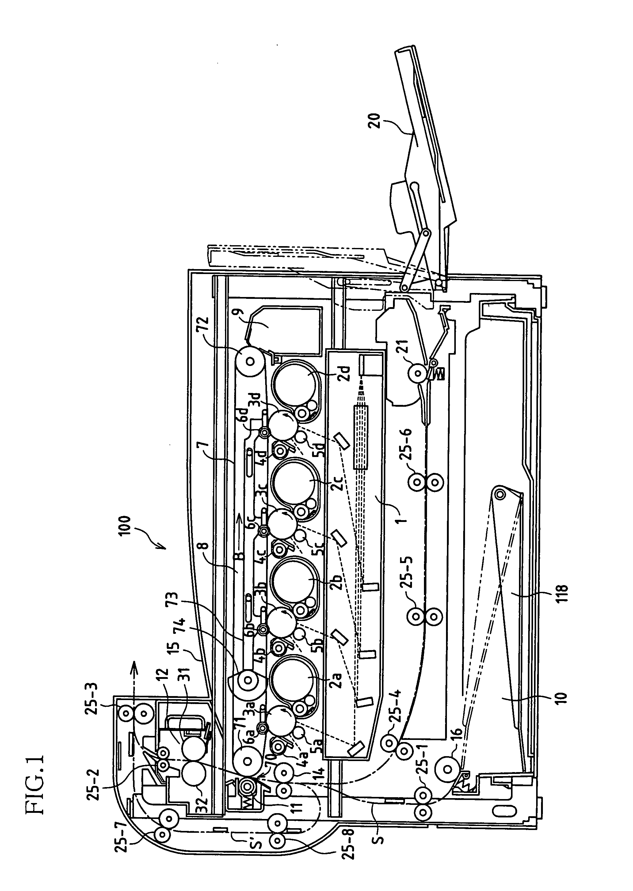
[0055]As shown in FIG. 1, an image forming apparatus 100 according to working example 1 is provided with an image reading system (omitted from drawing), an image forming system, a paper transport system, and a control system. The following is a description of the components therein.
[0056]—Description of Image Reading System—
[0057]An image reading system of the image forming apparatus 100 according to working example 1 includes a scanner portion (omitted from drawing) arranged in an upper part of the image forming apparatus. The scanner portion reads images such as an image of a manuscript placed on a document table (omitted from drawing) made of a material such as transparent glass and images of manuscripts supplied sheet by sheet by an unshown automatic paper supply portion (omitted from drawing), and generates manuscript image data.
[0058]—Description of Image Forming System—
[0059]As shown in FIG. 1, an image forming ...
working example 2
[0128]Next, description is given of an image forming apparatus according to a working example 2 using the accompanying drawings. It should be noted that the image forming apparatus according to working example 2 has a paper supply portion of a configuration different from working example 1 described above. Accordingly, description is given of working example 2 in regard to components different from working example 1 while description of equivalent components is omitted. For this reason, in regard to operational effects and modified examples of equivalent components, these have the same operational effects and modified examples as the above-described working example 1.
[0129]As shown in FIGS. 11 and 12, the paper supply portion of working example 2 is constituted by three paper supply cassettes 10a, 10b, and 10c. According to his / her use, a user can select any of the sheets of paper P supplied in the paper supply cassettes 10a, 10b, and 10c to use. It should be noted that the paper su...
working example 3
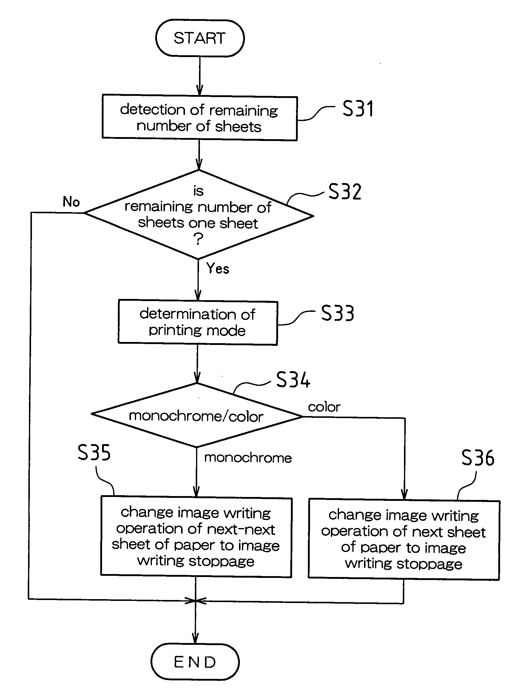
[0136]Next, description is given of an image forming apparatus according to a working example 3 using the accompanying drawings. It should be noted that the image forming apparatus according to working example 3 has an image writing sequence change timing different from working example 1 described above. In particular, working example 3 has a configuration relating to switching of multicolor (color) and single color (monochrome) image forming for sheets of paper P stored in the same paper supply cassette 10. Accordingly, description is given of working example 3 in regard to components different from working example 1 while description of equivalent components is omitted. For this reason, in regard to operational effects and modified examples of equivalent components, these have the same operational effects and modified examples as the above-described working example 1. Furthermore, in regard to the above-described working example 2 also, only the components of the paper supply port...
PUM
 Abstract
Description
Claims
Application Information
 - R&D
- Intellectual Property
- Life Sciences
- Materials
- Tech Scout
- Unparalleled Data Quality
- Higher Quality Content
- 60% Fewer Hallucinations
Browse by: Latest US Patents, China's latest patents, Technical Efficacy Thesaurus, Application Domain, Technology Topic, Popular Technical Reports.
© 2025 PatSnap. All rights reserved.Legal|Privacy policy|Modern Slavery Act Transparency Statement|Sitemap|About US| Contact US: help@patsnap.com