
Method and apparatus for frame interpolation

a frame interpolation and frame technology, applied in image data processing, television systems, standards conversion, etc., can solve problems such as motion judder, problems in moving areas of displayed, and only 50 frames per second of standard television broadcast transmissions, and achieve the effect of more simple and computationally efficien

Active Publication Date: 2008-01-10
VESTEL ELEKTRONIK SANAYI & TICARET ANONIM SIRKETI
View PDF3 Cites 17 Cited by
  • Summary
  • Abstract
  • Description
  • Claims
  • Application Information

AI Technical Summary

Benefits of technology

[0013] The method requires the steps of segmenting the or each of the identified moving objects and once this has been done determining motion parameters for each of the identified objects. In contrast to conventional methods of frame interpolation where motion parameters are determined for objects prior to segmentation using block or pixel based approaches (one motion parameter is determined for each pixel or block), in embodiments of the present invention the motion parameter estimation is performed after segmentation. This enables a reduction in the complexity of the motion parameter estimation since there are fewer object segments than pixels or pixel blocks.
[0019] Furthermore in some know methods, such as that described in US-A-2003 / 0194151, a so-called “segmentation” process requires analysis of each entire frame so as to identify motion vectors for each and every pixel in the image. This is complex and computationally expensive. In contrast in an embodiment of the present invention, segmentation only occurs in relation to moving objects within an image. Thus an algorithm used to perform the image processing is more simple and computationally efficient.

Problems solved by technology

However, standard television broadcast transmissions only contain 50 frames per second.
Motion judder is a problem that can arise in such situations with some types of up-conversion that are currently used.
This is an acceptable solution in static regions but problems occur in moving areas of the displayed video.
The problems are referred to as “motion judder” and blur and they cause degradation in visual quality which is undesirable.
The algorithm is extremely complex and expensive computationally.

Method used


Image

  • Method and apparatus for frame interpolation
  • Method and apparatus for frame interpolation
  • Method and apparatus for frame interpolation

Examples


Embodiment Construction

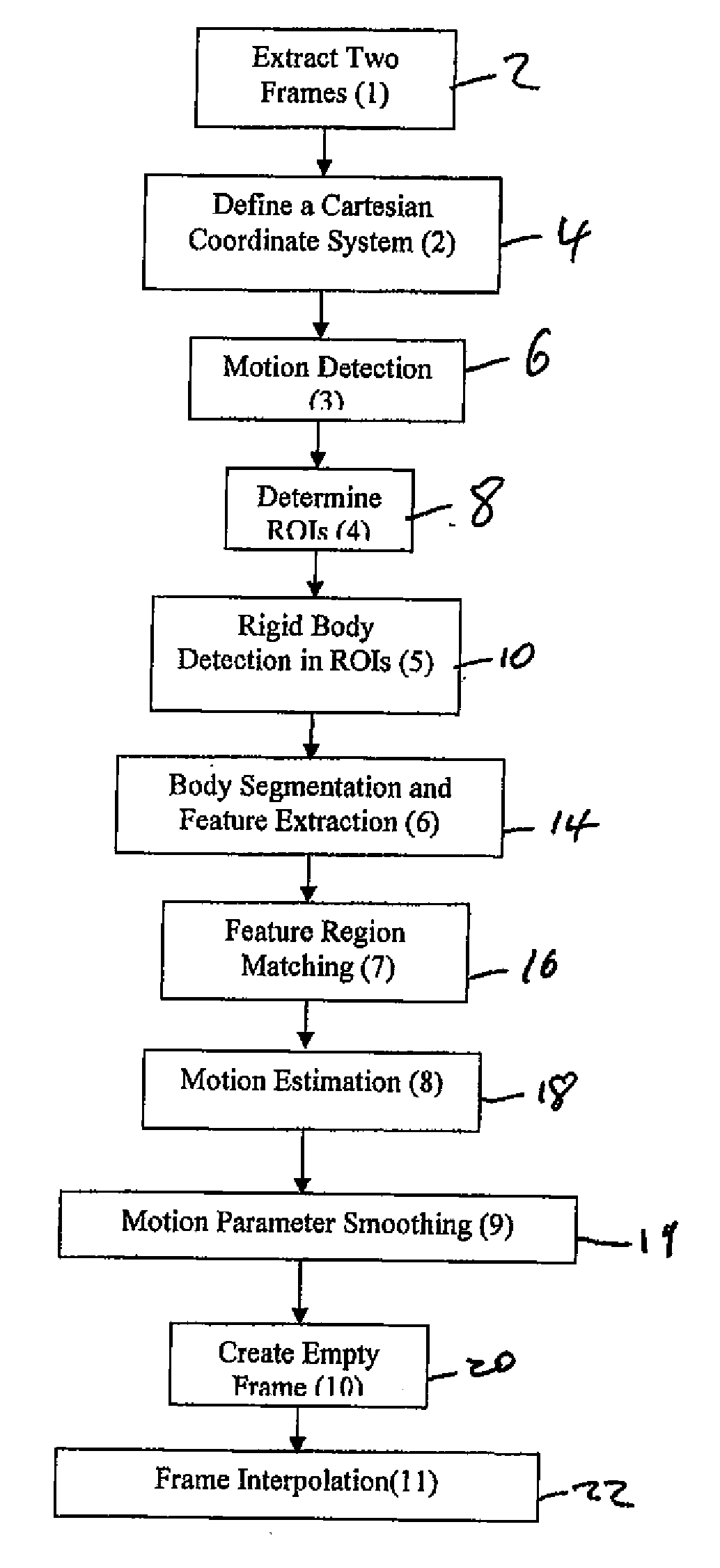
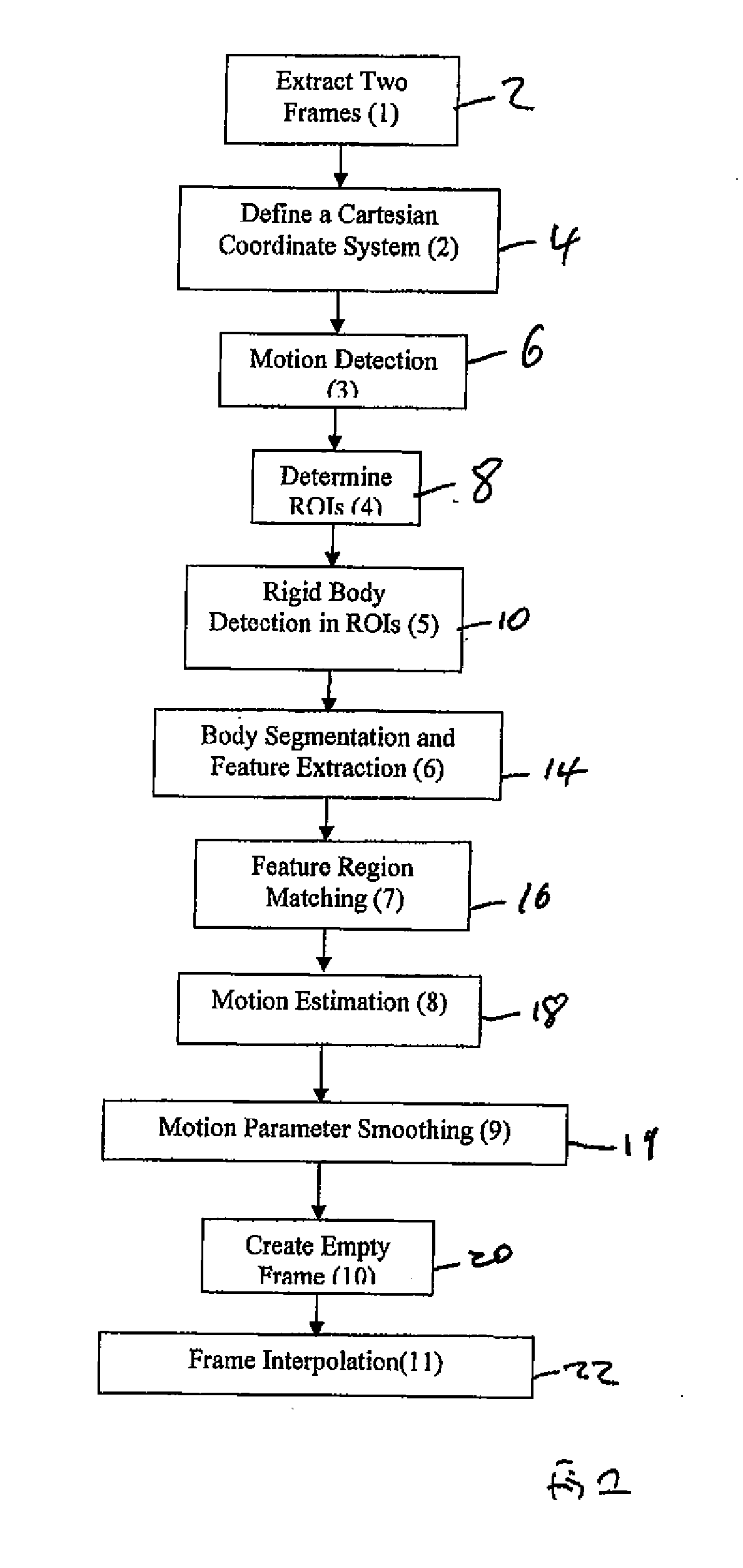
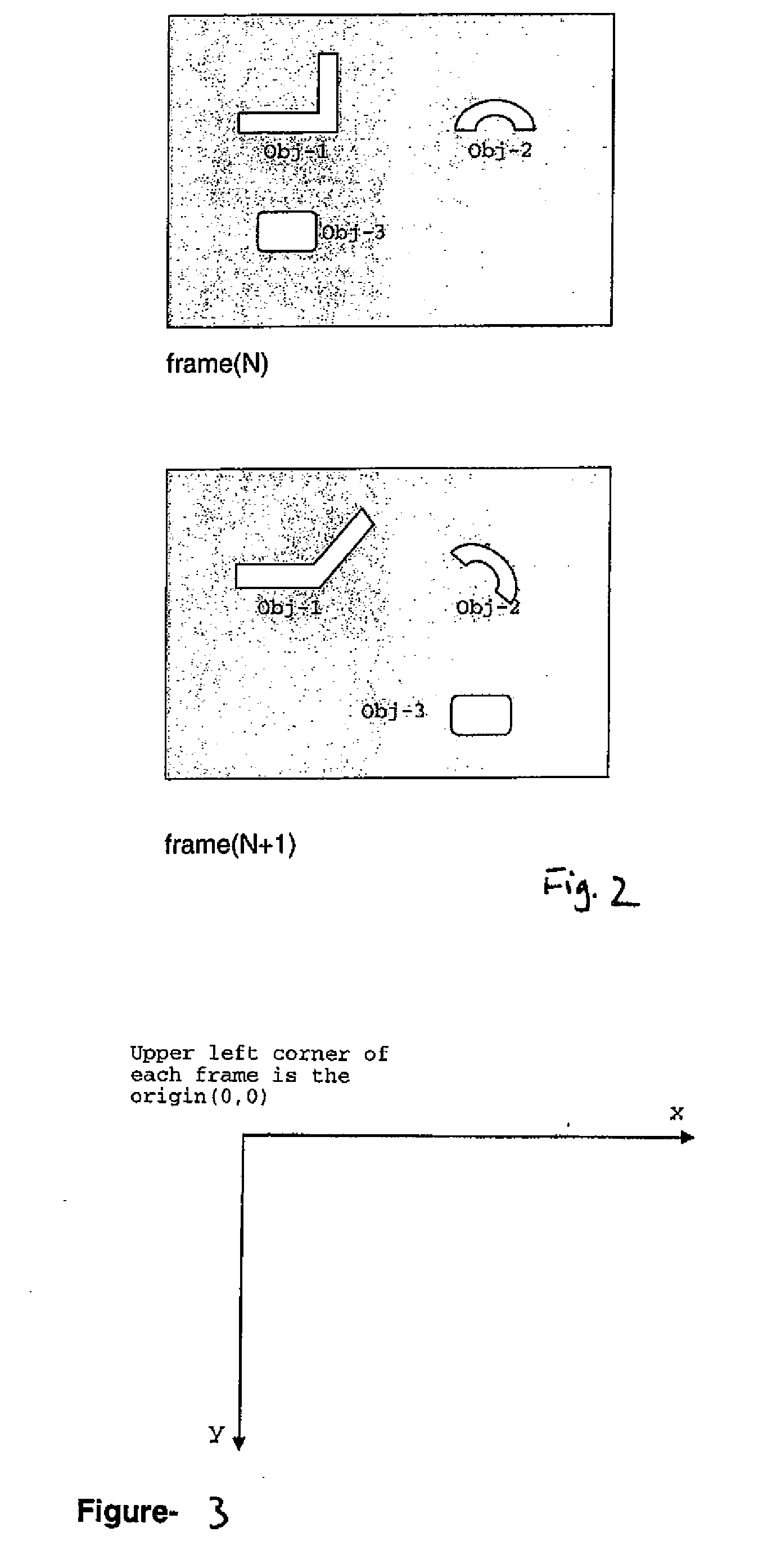
[0040]FIG. 1 is a schematic flow diagram of the steps of a method according to a particular embodiment of the present invention. Initially, at step 2, two consecutive frames are extracted from a first video stream to be processed. Next, at step 4, a coordinate system is defined for the extracted frames, such as a Cartesian coordinate system. Next, at steps 6 and 8 moving areas within the consecutive extracted frames are detected and the regions of the extracted frames in which the moving pixels are positioned are identified as regions of interest ROI. At step 10 object detection within the ROIs is performed to identify rigid bodies within the ROIs. A rigid body need not be a singular item with respect to the subject matter of the frame. Rather, it is a system of particles or component parts in which the relative distance between the particles or component parts does not vary.

[0041] At step 14 object segmentation and feature extraction is performed. The detected bodies are segmented...


PUM


Abstract

The invention provides a method of frame interpolation, the method comprising: receiving first and second frames from an input video stream; generating an interpolated frame for arranging between the first and second frames in a processed video stream so that the second video stream has a different higher frame rate than the input video stream, wherein generating the interpolated frame comprises: identifying one or more moving objects within the first frame; segmenting the or each of the identified moving objects; and, determining motion parameters for each of the segments of the segmented objects.

Description

CROSS-REFERENCE TO RELATED APPLICATION [0001] This application claims the benefit of priority to U.S. Application Ser. No. 60 / 803,538 filed May 31, 2006, the content of which is hereby incorporated by reference in its entirety for all purposes.FIELD OF THE INVENTION [0002] The present invention relates to a method and apparatus for frame interpolation. In embodiments the invention also relates to a television set including an apparatus for frame interpolation. BACKGROUND OF THE INVENTION [0003] A video is made up of plural frames, each frame being a still image, the effect of showing consecutive frames being to give the impression of movement. The frame rate of videos is generally sufficiently high such that a viewer cannot perceive the individual frames but rather perceives a continuous moving image. [0004] On some television displays it is desirable to increase the frame rate from that at which the video being displayed was originally captured. This can be due to increase frame ra...

Claims


Application Information

Patent Timeline
Patent Type & Authority Applications(United States)
IPC IPC(8): H04N7/12H04N11/02H04N7/01
CPCG06T3/4007H04N5/145H04N19/577H04N7/0137H04N7/0127
Inventor OZDEMIR, HUSEYIN
Owner VESTEL ELEKTRONIK SANAYI & TICARET ANONIM SIRKETI
Learn More