
Apparatus and method for measuring the signal from a fluorescing nanodrop contained by surface tension

a surface tension and nanodrop technology, applied in the field of spectrofluorometry, can solve the problems of insufficient application of the type disclosed in the referenced robertson patents to the measurement of a fluorescing nanodrop, interference with the much less intense light produced by the sample fluorescence itself, and inability to meet the requirements of fluorescence measurement, etc., to achieve the effect of minimizing the transmission of unwanted light and increasing the unwanted ambient and background excitation light energy

Inactive Publication Date: 2008-01-03
NANODROP TECH LLC
View PDF12 Cites 13 Cited by
  • Summary
  • Abstract
  • Description
  • Claims
  • Application Information

AI Technical Summary

Benefits of technology

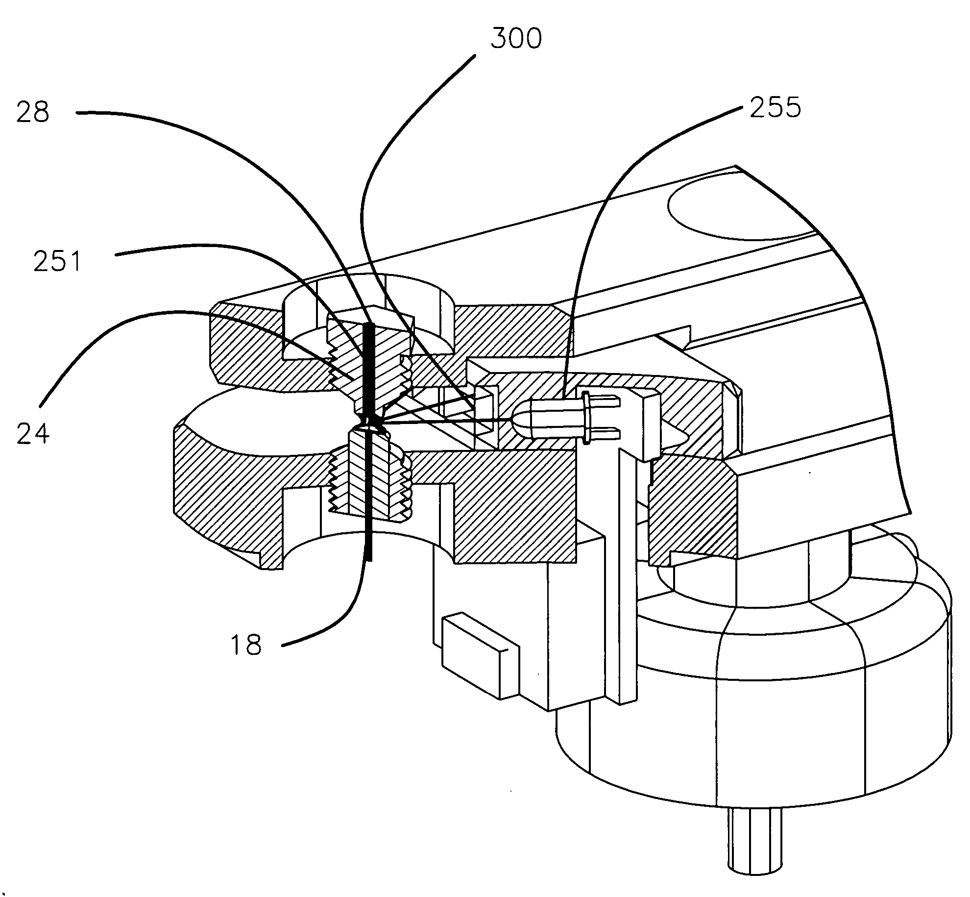
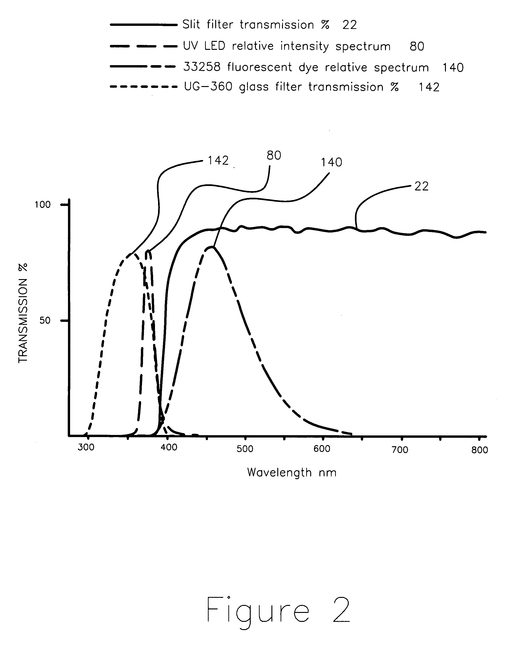
[0019] A preferred embodiment of the method of operating the apparatus includes compensation for any exciting and ambient light that does impinge on the measuring sensor. This is accomplished by removing instrumentation and background contributions from the signal by separately measuring them and subtracting their spectra from the sample measurement spectrum. The very high rejection multimode optical fibers have for light incident at angles significantly above the angle of the optical fiber transmission numerical aperture and the reduction in scattering as a result of wetting or optical contact of all optical surfaces associated with the sample measurement is sufficient to reduce the background light from the source to a level where it is feasible to extract the fluorescence by simply subtracting a scaled representation of the source, the principle improvement which is being called virtual filtering.
[0040] The means for signal modification provided at the distal end of the second fiber can vary from signal gain to nearly complete damping of the signal in that optical fiber. In the former instance a mirrored surface cap is provided at the end of the fiber. This has the effect of returning the fluorescent emission in the fiber to be transmitted back through the sample to the sensor. In most instances of practical use, it has been found that such a configuration tends also to increase unwanted ambient and background excitation light energy. The other instance employs means to form an energy-absorbing surface to minimize transmission of unwanted light to the measuring sensor. Drawing the fiber to a long thin point can do this, as can ending the fiber with or into an absorbing coating or surface or making the fiber using a glass that is highly absorbing throughout the fluorescence and excitation wavelength range.

Problems solved by technology

Measurements of the type disclosed in the referenced Robertson patents, however, are not optimally applicable to measurement of a fluorescing nanodrop.
However the light handling system of the two, prior-art, Robertson inventions tends to overwhelm a fluoroscopic measurement particularly so when a weakly emitting or fluorescing sample is involved.
Light used to excite the fluorescence projected from one in-line optical fiber through the drawn column of fluid to excite fluorescence in the contained nanodrop and directly into an in-line receiving optical fiber to a sensor interferes with the much less intense light produced by the sample fluorescence itself.

Method used


Image

  • Apparatus and method for measuring the signal from a fluorescing nanodrop contained by surface tension
  • Apparatus and method for measuring the signal from a fluorescing nanodrop contained by surface tension
  • Apparatus and method for measuring the signal from a fluorescing nanodrop contained by surface tension

Examples


example 1

Emission Spectra of a Donor—Acceptor FRET (Fluorescence Resonance Energy Transfer) Pair and Its Positive Control

[0067] The FRET pair was constrained in a hairpin configuration comprised of a single-stranded nucleotide probe (loop) and a double-stranded nucleotide (stem) structure. The fluorescence donor (fluorescein) was covalently attached at one end and an acceptor (Cy5) covalently attached to the other end of the stem. Thus, In the absence of the complimentary nucleotide sequence to the probe (loop), the hairpin's double-stranded (base-paired) stem structure is conserved. The excited donor's fluorescence 510 was proportionally transferred to the acceptor resulting in longer wavelength fluorescence emission 540 at wavelength 530. In the presence of the complimentary sequence to the single-stranded probe (loop), the hairpin's base-paired stem structure was disrupted, double-stranded probe was formed, and the resonance energy from the excited donor 510 was not transferred 520 to th...

example 2

Virtual-Filtered Emission Spectrum of a Solution Containing Four Fluorophores Excited with an Unfiltered White LED

[0068] Complex mixtures of fluorophores having excitation maxima differing by 200 nm have been excited using a single broad wavelength unfiltered white LED source, shown as 140 in FIG. 4. The resulting virtual-filtered emission spectrum of four fluorophores, each differing by approximately 50 nm within the wavelength boundary 270, was displayed and labeled as 550.


PUM


Abstract

Apparatus and method for measuring the fluorescence of nanodrop liquid samples is described in which the sample is held by surface tension between two anvil surfaces. Each anvil surface has an embedded optical fiber with its end finished flush with the surface in the containment area wetted by the sample with the fiber in line. Sample excitation is provided from the side of the sample remote from the containment area. By selection of the fiber transmission numeric aperture the impact of exciting and ambient light on the measurement is minimized. A method of virtual filtering is taught in which any ambient or exciting light that does impinge on the measuring sensor is corrected by subtracting a scaled representation of the source from the measurement. The method and apparatus is capable of detecting 1 femptomole of sodium fluorescein in 1 microliter of TE buffer.

Description

FIELD OF THE INVENTION [0001] The invention relates to the field of spectrofluorometry and its use in quantitating and or characterizing liquids and solutions. More particularly it relates to the fluorometry of nanodrop liquids and even more particularly to such nanodrops contained by surface tension. BACKGROUND OF THE INVENTION [0002] Low sample volume instruments that work in the range of 2 microliters or less are particularly useful in the quantitation of biotechnology samples including nucleic acids, proteins and drugs and any other liquid samples where it is desirable to keep the volume of the sample loss to a minimum where available analyte quantity is very limited and where convenience of measurement is desired. [0003] Prior art concentrates on the containment of samples in vessels or containers wherein the sample volume is usually from 20 to 1000 microliters. A relatively straightforward spectrofluorometer design can be seen in Nogami et al. U.S. Pat. No. 5,500,536. A spectr...

Claims


Application Information

Patent Timeline
Patent Type & Authority Applications(United States)
IPC IPC(8): G01J3/00G01J3/30
CPCG01N21/645G01N2021/6484G01N2021/035
Inventor ROBERTSON, CHARLES WILLIAMHANSEN, JOEL BRUCE
Owner NANODROP TECH LLC
Learn More