Axial Flux Induction Electric Machine

Inactive Publication Date: 2008-01-03
AXCO MOTORS OY
View PDF10 Cites 47 Cited by
  • Summary
  • Abstract
  • Description
  • Claims
  • Application Information

AI Technical Summary

Benefits of technology

[0006] It is an object of the present invention to eliminate the aforementioned drawbacks. The object of the invention in particular is to introduce a novel axial flux induction machine, the configuration of which is simple and compact and which endures also high rotation speeds, above 10,000 rpm, and even above 30,000 rpm, and which can be conveniently integrated with various power tools such as, for instance, pumps, blowers, and compressors. SUMMARY OF THE INVENTION
[0010] In common induction motors instead, as pure aluminum as possible is often used in casting the cage windings of the rotor of the machine. A surprising feature of the invention is the application of appropriately composed aluminum alloy both in the electrically conductive structure and in the actual rotor frame structure. In the invention, application of a suitable copper alloy may similarly come into question. In this rotor steel is used as a path for the magnetic flux, whereas in the commonly known technique steel parts comprise the load-bearing structures of the rotor. When using strong aluminum or copper in the entire rotor, that is, both in the rotor frame and in the short-circuit rings, a firm structure is achieved that endures well also the centrifugal forces caused by the ferromagnetic parts in the rotor.
[0013] In an embodiment of the invention, on the surface of the rotor frame and / or between the rotor plates, there are blades or other corresponding motor parts in order to produce the cooling air flow. For this purpose, there may be axial holes in the rotor, through which the air can flow to the blades positioned between the rotor plates or to other corresponding ventilating ducts. With the created air currents it is possible to efficiently cool the stator, the rotor, and other parts of the motor.
[0014] It is also possible that blower blades are integrated into the rotor surface, in which case the blower and the motor rotating it together have as few rotating surfaces as possible. Hence the surface frictions can be minimized, which in high rotation speeds significantly improves the efficiency of the entire configuration.
[0021] The construction of the invention has significant advantages when compared with the known technology. The machine configuration as a whole becomes very short, it is easy to integrate with power tools, and it is easy to manufacture. The rotor of the invention is very durable when compared with traditional rotor constructions, which enables high rotation speeds.

Problems solved by technology

Pure aluminum conducts electricity better than aluminum alloys, but it is mechanically brittle, and therefore its application in high-speed machines cannot be justified.

Method used


Image

  • Axial Flux Induction Electric Machine
  • Axial Flux Induction Electric Machine
  • Axial Flux Induction Electric Machine

Examples


second embodiment

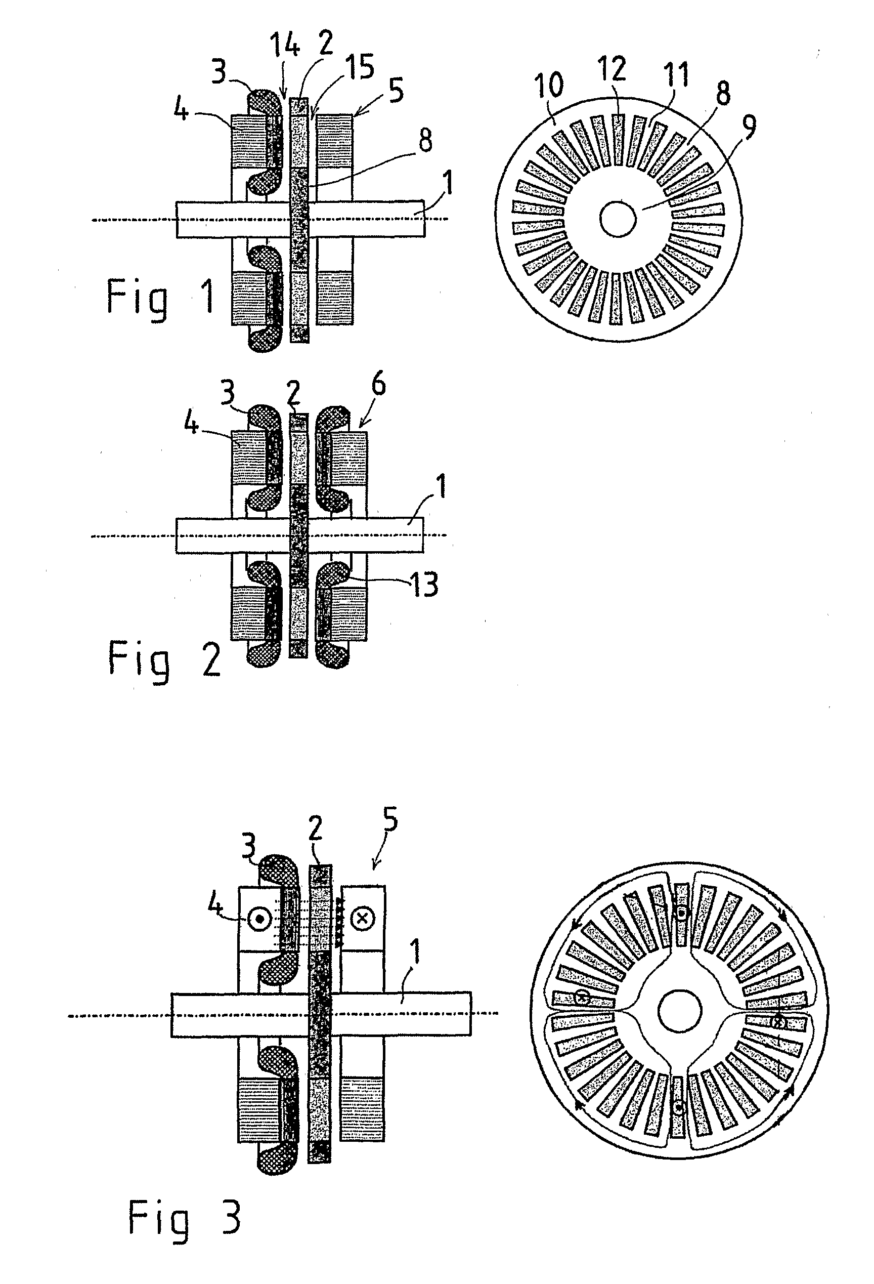
[0032] In FIG. 2 the rotor 2 and the stator 4 are similar to the embodiment of FIG. 1. The element 6 to conduct the magnetic flux instead is a construction corresponding to the stator 4, comprising the stator winding 13.

[0033] The paths of the magnetic flux and of the current in the machine construction of the electrical machine of FIG. 1 are indicated in FIG. 3.

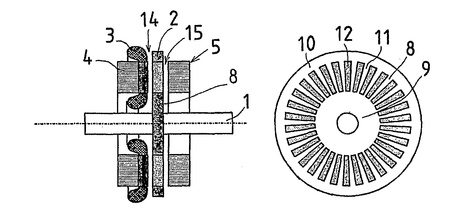
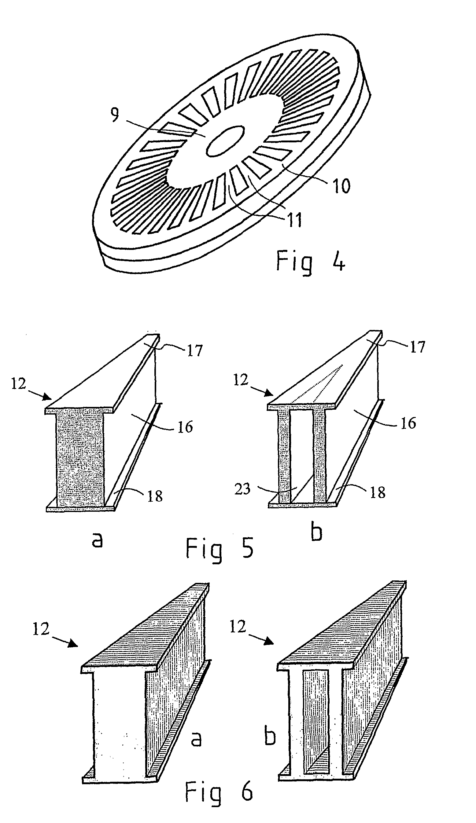
[0034]FIG. 4 shows a further detailed view of the rotor embodiment of the invention comprising two plates joined together. The plates have been machined for instance by precision stamping from work-hardened aluminum alloy sheet. The frame plate 8 formed of the cage winding comprises a uniform inner periphery 9 and a uniform outer periphery 10 and conductor bars 11 of the same material, the conductor bars galvanically connecting the peripheries. The conductor bars are bars of equal size extending in the direction of the rotor radius, located at even distances between the inner and outer peripheries. Between the peripheries a...

third embodiment

[0039]FIG. 7 further shows, in a way corresponding to that of FIGS. 1 and 2, the invention in which a solid ferromagnetic steel plate with teeth fitted in the apertures of the aluminum rotor is fixed to the surface of the rotor 2 on the opposite side of the stator 4 to function as an element 7 to conduct the magnetic flux. Thus the ferromagnetic teeth projecting through the aluminum cage of the rotor and the uniform ferromagnetic plate located on the backside of the rotor viewed from the stator together form a path for the magnetic flux.

[0040] The dashed lines in FIG. 7 further indicate an embodiment of the invention in which blades 19 have been arranged on the outer surface of the steel plate 7 close to its outer periphery. These blades can be machined to the steel plate or they may be separate structures attached with an appropriate method to the steel plate 7. An efficient blower in which the surface friction caused by rotating surfaces has been minimized, is achieved easily and ...


PUM


Abstract

The invention relates to an axial flux induction electrical machine comprising a frame, a shaft (1) bearing-mounted to the frame, a disc-like rotor (2) supported to the shaft, a stator (4) comprising a stator winding (3) and supported by the frame on the first side of the rotor in axial direction. The disc-like rotor (2) comprises a non-ferromagnetic rotor frame (8) fabricated of a material with high electrical conductivity and comprising a uniform inner periphery (9) and an outer periphery (10) and conductor bars (11) fabricated of the same material and galvanically connecting the peripheries (11), the conductor bars together with the inner and outer peripheries forming in addition to the rotor frame also the cage winding of the rotor. In addition, between the inner periphery and the outer periphery there is a plurality of ferromagnetic pieces (12) extending through the frame plate and being spaced apart from each other at an appropriate distance so that the radial conductor bars are appropriately located between the pieces. According to the invention, the disc-like rotor frame (8) comprises at least one circular plate machined of work-hardened metal sheet.

Description

FIELD OF THE INVENTION [0001] The invention relates to an axial flux induction electrical machine as defined in the preamble of claim 1. The invention is chiefly developed to function as a motor, but also different generator embodiments may come into question. BACKGROUND OF THE INVENTION [0002] An axial flux machine as such is not by nature very well applicable as a high-speed induction machine, because the characteristics of an induction machine are usually the best when there are only few poles (two, or four at the maximum) in the machine. However, a two-pole solution is often unsuitable for an axial flux machine, because the end-winding arrangement of the stator winding is not often a functional solution in a two-pole machine. Therefore, also a high-speed axial flux machine has usually to be designed at least as a four-pole configuration. In that case both the magnetic flux in the stator yoke and the current of the machine in the windings have to flow a quarter of the inner and o...

Claims


Application Information

Patent Timeline
IPC IPC(8): H02K17/16H02K15/02H02K9/06H02K
CPCH02K17/165H02K17/20
Inventor PYRHONEN, JUHAPIISPANEN, ARI
Owner AXCO MOTORS OY
Why Eureka
Try Eureka