Voltage generating apparatus, current generating apparatus, and test apparatus

Active Publication Date: 2007-12-27
ADVANTEST CORP
View PDF3 Cites 8 Cited by
  • Summary
  • Abstract
  • Description
  • Claims
  • Application Information

AI Technical Summary

Benefits of technology

[0011]According to the third aspect of the present invention, there is provided a test apparatus that tests a device under test. The test apparatus includes: a voltage generating apparatus that outputs a power source voltage to be supplied to the device under test from a voltage outputting terminal; and a test processing section that tests the device under test in a state that the voltage generating apparatus has supplied the power source voltage to the device under test, in which the voltage generating apparatus includes: a voltage outputting section that outputs the power source voltage according to a current or voltage to be input; a first differential amplification section that compares the power source voltage and a preset first reference voltage to output a first control current or voltage reducing the power source voltage output from the voltage outputting section when the power source voltage is larger than the first reference voltage and output the first control current or voltage raising the power source voltage output from the voltage outputting section when the power source voltage is smaller than the first reference voltage; a current detector that detects a detecting voltage according to a power source current output from the voltage outputting terminal; a second differential amplification section that compares the detecting voltage detected from the current detector and a second reference voltage to output a second control current or voltage reducing the power source voltage when a value obtained by subtracting the second reference voltage from the detecting voltage is larger; an addition section that inputs a current or voltage obtained by adding the first control current or voltage and the second control current or voltage into the voltage outputting section; and a third differential amplification section that supplies a voltage obtained by amplifying a difference voltage obtained by subtracting the detecting voltage from a preset third reference voltage to the second differential amplification section as the second reference voltage.
[0012]According to the fourth aspect of the present invention, there is provided a test apparatus that tests a device under test. The test apparatus includes: a current generating apparatus that outputs a power source current to be supplied to the device under test from a current outputting terminal; and a test processing section that tests the device under test in a state that the current generating apparatus has supplied the power source current to the device under test, in which the current generating apparatus includes: a current outputting section that outputs the power source current according to a current or voltage to be input; a current detector that detects the power source current output from the current outputting terminal; a fourth differential amplification section that compares the power source current and a preset first reference current to output a first control current or voltage reducing the power source current output from the current outputting section when the power source current is larger than the first reference current and output the first control current or voltage raising the power source current output from the current outputting section when the power source current is smaller than the first reference current; a fifth differential amplification section that compares a power source voltage at the current outputting terminal and a second reference voltage to output a second control current or voltage reducing the power source current when a value obtained by subtracting the second reference voltage from the power source voltage is larger; an addition section that inputs a current or voltage obtained by adding the first control current or voltage and the second control current or voltage into the current outputting section; and a sixth differential amplification section that supplies a voltage obtained by amplifying a difference voltage obtained by subtracting the power source voltage from a preset third reference voltage to the fifth differential amplification section as the second reference voltage.

Problems solved by technology

When the power source current ISHORT at the load short is large, a conventional voltage generating apparatus may flow a large current into a load to destroy the load.

Method used


Image

  • Voltage generating apparatus, current generating apparatus, and test apparatus
  • Voltage generating apparatus, current generating apparatus, and test apparatus
  • Voltage generating apparatus, current generating apparatus, and test apparatus

Examples


Embodiment Construction

[0021]The invention will now be described based on the preferred embodiments, which do not intend to limit the scope of the present invention, but exemplify the invention. All of the features and the combinations thereof described in the embodiment are not necessarily essential to the invention.

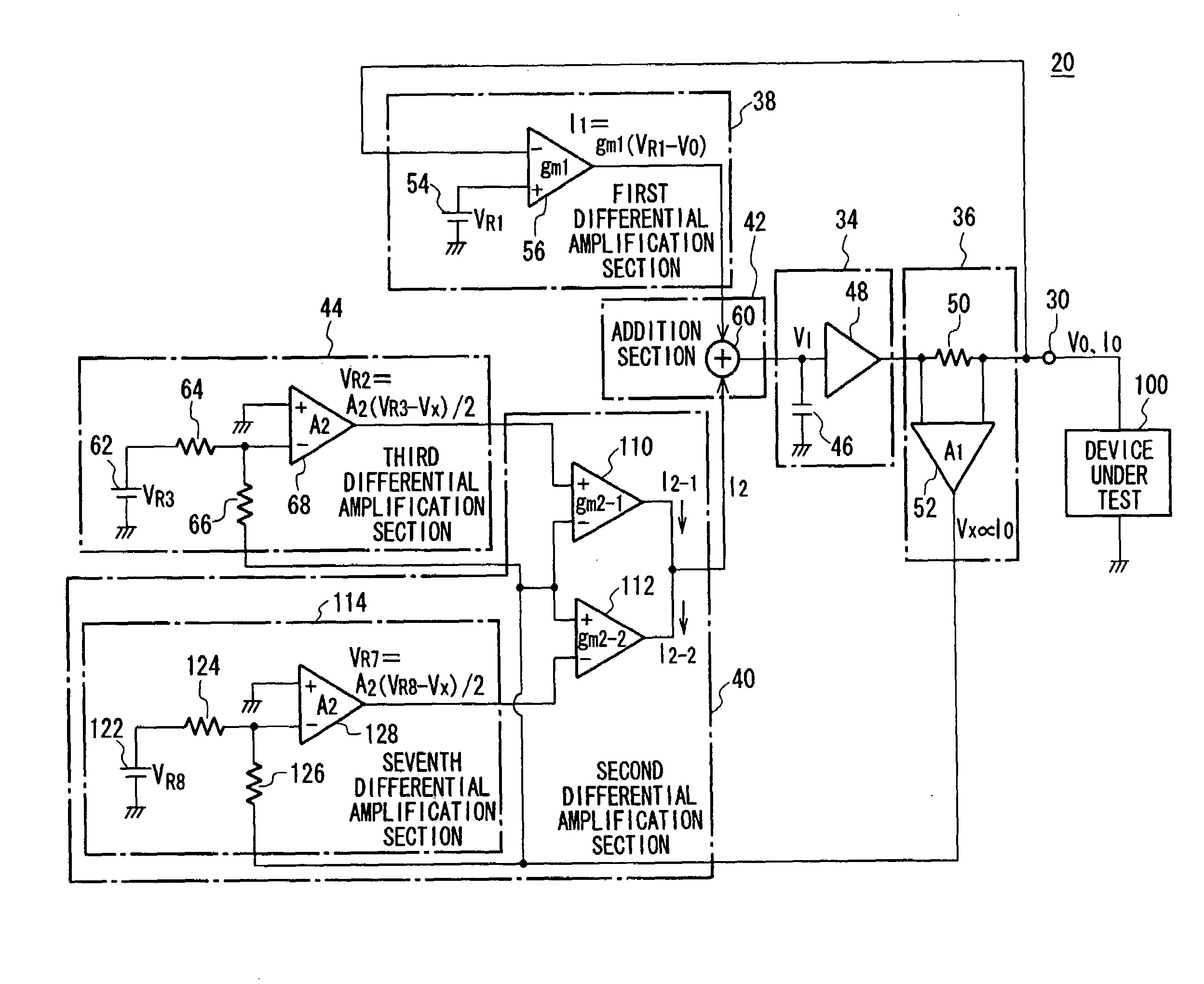
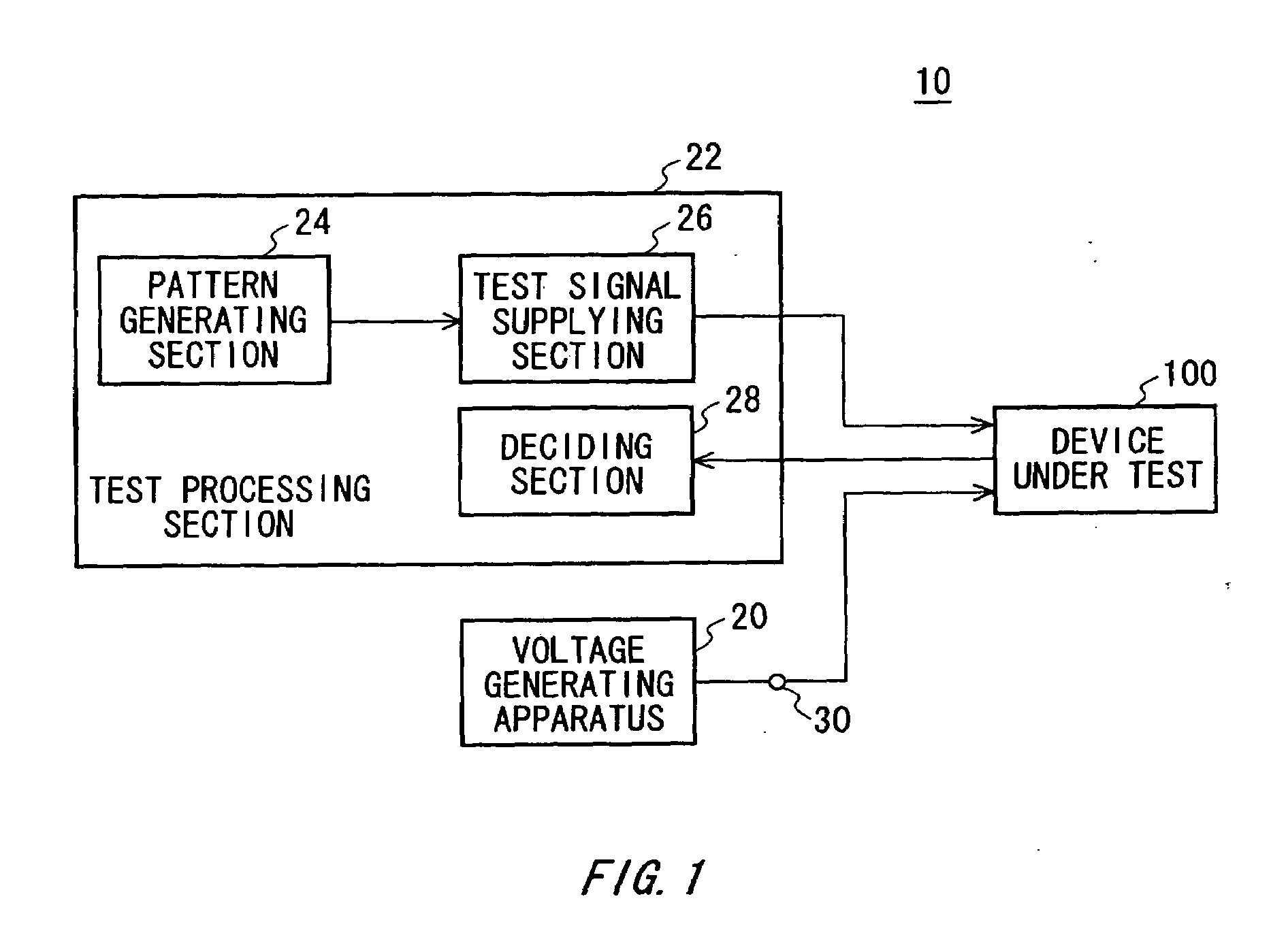
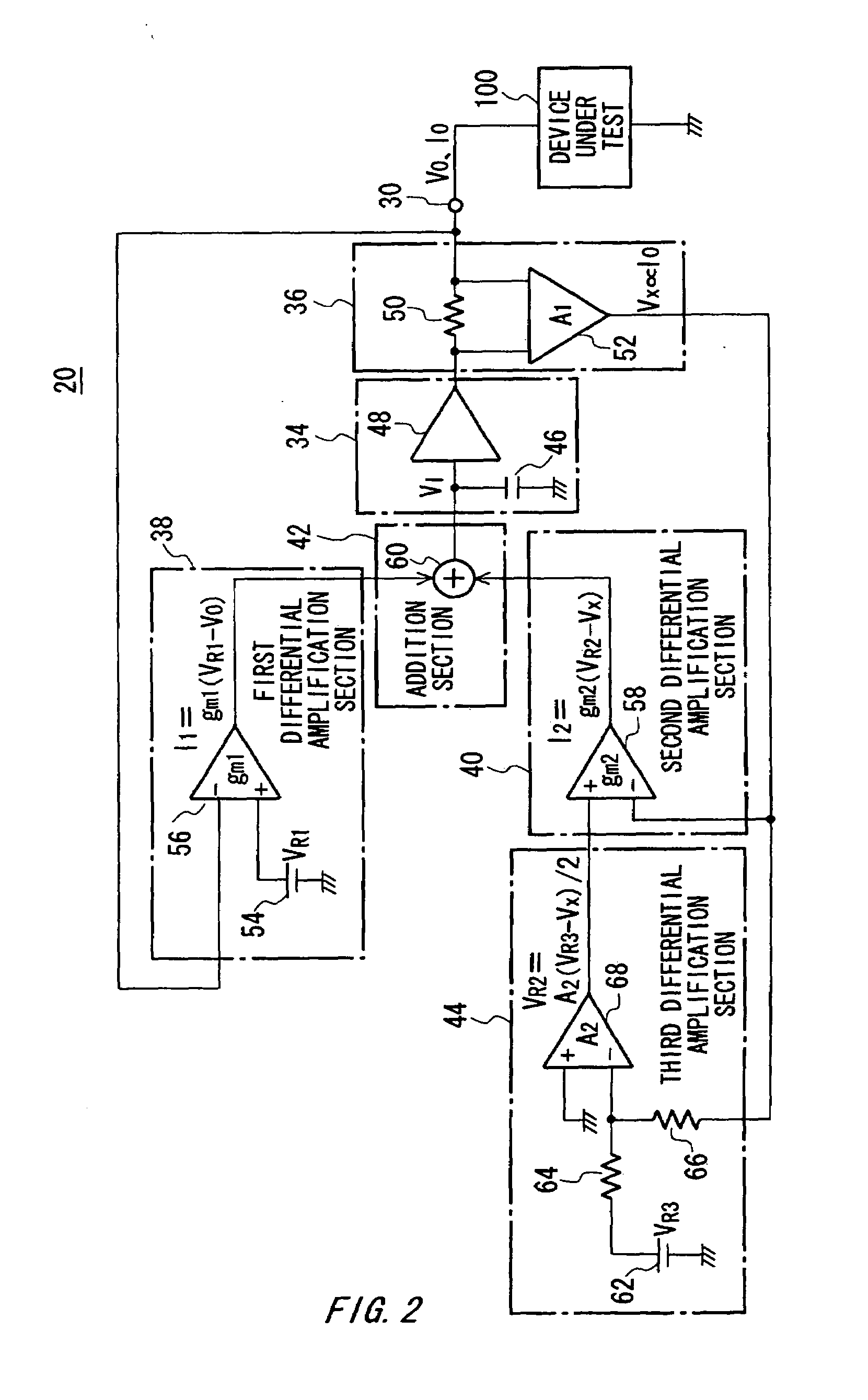
[0022]FIG. 1 is a view showing a configuration of a test apparatus 10 according to an embodiment along with a device under test 100. The test apparatus 10 includes a voltage generating apparatus 20 and a test processing section 22, and tests the device under test 100. The voltage generating apparatus 20 outputs a power source voltage VO to be supplied to the device under test 100 from a voltage outputting terminal 30 thereof. The test processing section 22 tests the device under test 100 in a state that the voltage generating apparatus 20 has supplied a power source voltage to the device under test 100. As an example, the test processing section 22 may have a pattern generating section 24, a ...


PUM


Abstract

There is provided a voltage generating apparatus that outputs a power source voltage from a voltage outputting terminal. The apparatus includes a voltage outputting section that outputs the power source voltage according to a current or voltage to be input, a first differential amplification section that compares the power source voltage and a preset first reference voltage to output a first control current or voltage reducing the power source voltage output from the voltage outputting section when the power source voltage is larger than the first reference voltage and output the first control current or voltage raising the power source voltage output from the voltage outputting section when the power source voltage is smaller than the first reference voltage, a current detector that detects a detecting voltage according to a power source current output from the voltage outputting terminal, a second differential amplification section that compares the detecting voltage detected from the current detector and a second reference voltage to output a second control current or voltage reducing the power source voltage when a value obtained by subtracting the second reference voltage from the detecting voltage is larger, an addition section that inputs a current or voltage obtained by adding the first control current or voltage and the second control current or voltage into the voltage outputting section, and a third differential amplification section that supplies a voltage obtained by amplifying a difference voltage obtained by subtracting the detecting voltage from a preset third reference voltage to the second differential amplification section as the second reference voltage.

Description

BACKGROUND OF THE INVENTION[0001]1. Field of the Invention[0002]The present invention relates to a voltage generating apparatus, a current generating apparatus, and a test apparatus. More particularly, the present invention relates to a voltage generating apparatus for outputting a power source voltage, a current generating apparatus for outputting a power source current, and a test apparatus for testing a device under test.[0003]2. Related Art[0004]FIG. 7 is a view showing relation of a power source voltage VO to a power source current IO in a voltage generating apparatus including a conventional current limiting circuit. Conventionally, there has been known a voltage generating apparatus including a current limiting circuit that limits an electric current so that the electric current exceeding a predetermined value does not flow into a load. The limiting circuit detects a power source current IO, and descends a power source voltage VO to constant gain when the detected power sourc...

Claims


Application Information

Patent Timeline
Patent Type & Authority Applications(United States)
IPC IPC(8): G01R7/00
CPCG01R31/2839
Inventor ANDOH, HIROKITANAKA, HIRONORI
Owner ADVANTEST CORP
Why Eureka
Try Eureka