
Nut having cutting and fastening structure thereof

Inactive Publication Date: 2007-12-20
ASUSTEK COMPUTER INC
View PDF18 Cites 2 Cited by
  • Summary
  • Abstract
  • Description
  • Claims
  • Application Information

AI Technical Summary

Benefits of technology

[0006]The objective of the present invention is to provide a nut having a cutting for increasing surface friction force and a fastening structure.

Problems solved by technology

But, once bolts and nuts did are not tightened tightly, the electronic apparatus may malfunction.
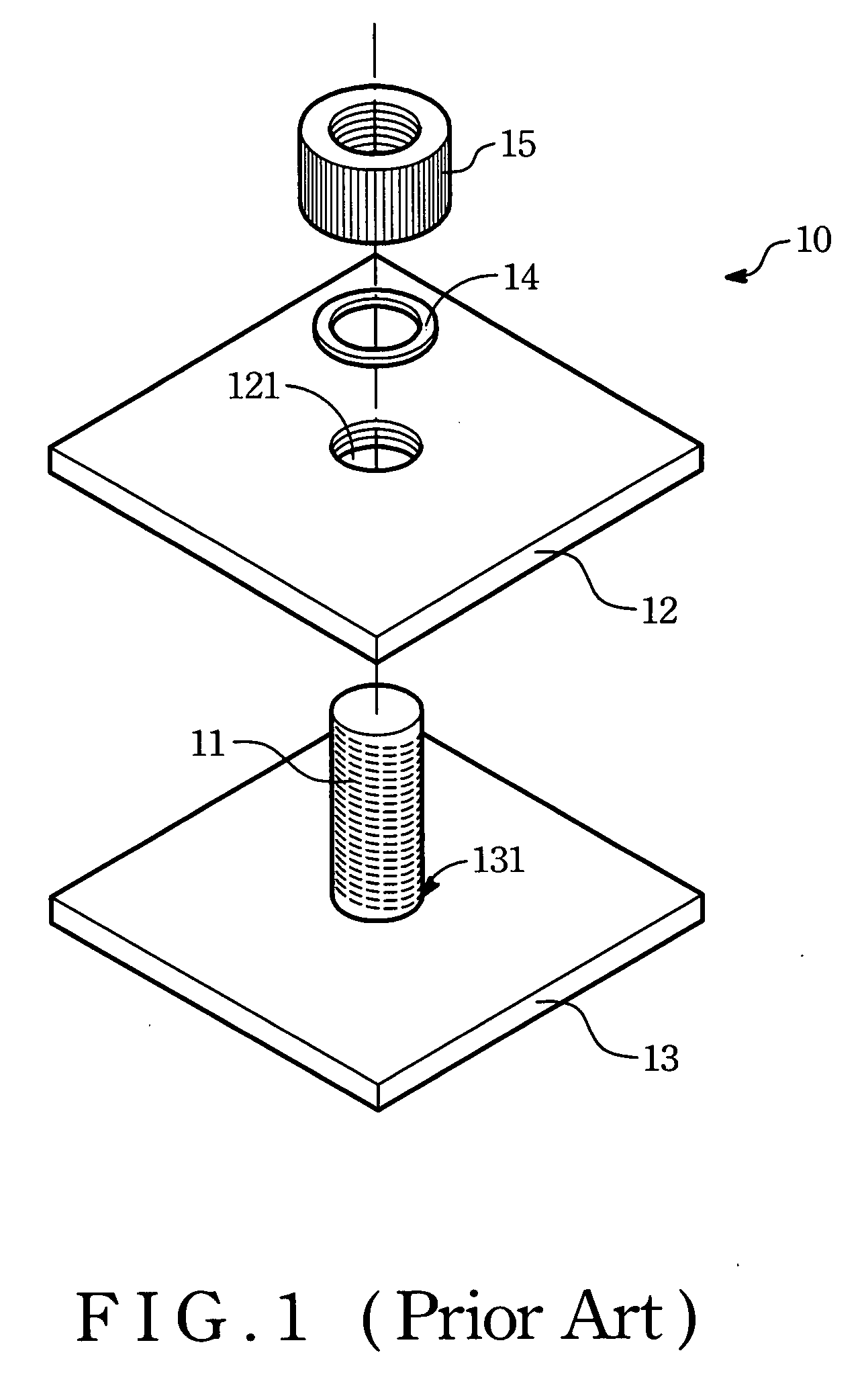
The above conventional fastening structure does not have good effect for preventing the nut movement.
The friction area between the spacer and the nut is not large enough, and the friction effect produced from threads of the bolt and the nut is limited.
Therefore, the nut of conventional fastening structure may be easily fall off or loose.
So, how to find an improved fastening structure to resolve the drawbacks of the prior art is an important issue for the persons skilled in the art.

Method used


Image

  • Nut having cutting and fastening structure thereof
  • Nut having cutting and fastening structure thereof
  • Nut having cutting and fastening structure thereof

Examples


Embodiment Construction

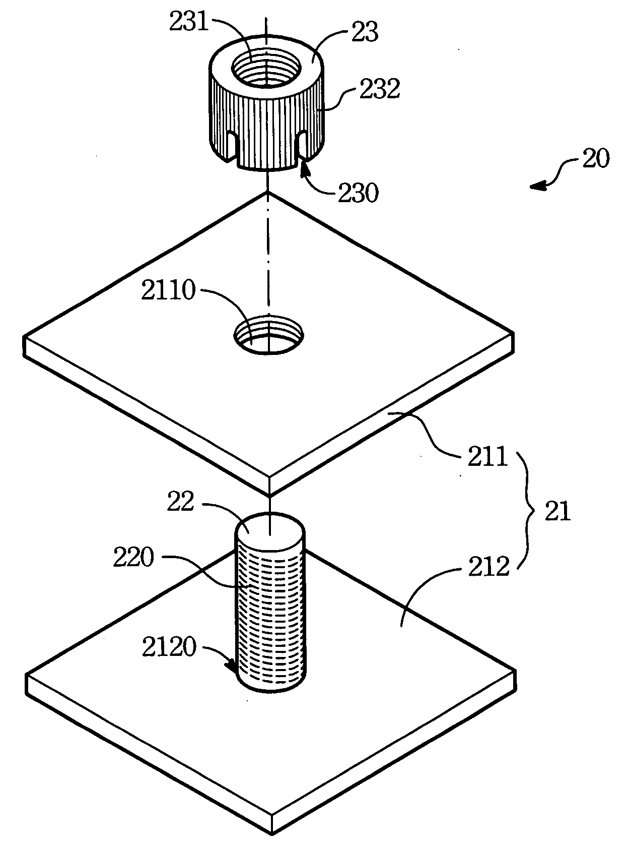
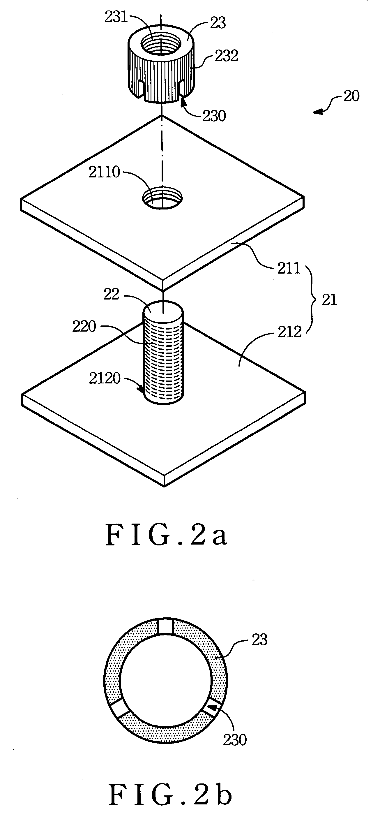
[0016]The preferred embodiment of the present invention discloses a nut with a cutting. The cutting reduces the contacting areas of a nut and a bolt so as to increase the friction force between the contacting areas.

[0017]Referring to FIG. 2a and FIG. 2b, FIG. 2a illustrates an exploded view of a fastening structure of a first preferred embodiment of the present invention. The fastening structure is applied to fix a board 21. FIG. 2b illustrates a bottom plan view of a nut of the FIG. 2a. A fastening structure 20 has a bolt 22 and a nut 23. As shown in FIG. 2a, the board 21 has an upper board 211 and a lower board 212, the upper board 211 and the lower board 212 individually have holes 2210, 2120. The bolt 22 passes through holes 2120, 2110, and the peripheral surface of the bolt 22 has a plurality of threads 220. The nut 23 is threaded on the bolt 22 and the threads 220 of the bolt 22 matches up the inner threads of the nut 23, thereby fastening the upper board 211 with the lower bo...


PUM


Abstract

A nut having a cutting and fastening structure thereof applied to fasten at least a board with a hole are disclosed. The nut has at least a cutting through itself. The fastening structure includes a bolt and a nut. When the nut is threaded on the bolt, the cutting of the nut and threads of the bolt touch each other for increasing the friction.

Description

FIELD OF THE INVENTION[0001]The present invention generally relates to a nut, more particularly to a nut having cutting of a fastening structure.DESCRIPTION OF THE RELATED ART[0002]With the electronic technology vigorous development, all kinds of electronic components are applied to make up the electronic apparatus. Bolts and nuts are extensively used to join the electronic components. But, once bolts and nuts did are not tightened tightly, the electronic apparatus may malfunction.[0003]Please refer to FIG. 1, which illustrates a schematic exploded view of a fastening structure of the bolt and the nut in prior arts. The fastening structure 10 includes a bolt 11, an upper board 12, a lower board 13, a spacer 14, and a nut 15. There are through holes 121, 131 for receiving the bolt 11 individually on the upper board 12 and the lower board 13. The nut 15 is threaded on the bolt 11 for forcing the upper board 12 and the lower board 13 together. The spacer 14 is placed between the hole 1...

Claims


Application Information

Patent Timeline
IPC IPC(8): F16B39/12
CPCF16B39/282F16B5/02
Inventor CHANG, ARTHURCHEN, FU-MING
Owner ASUSTEK COMPUTER INC
Learn More