
Apparatus for driving liquid crystal display and method thereof

a technology of liquid crystal display and apparatus, which is applied in the direction of instruments, static indicating devices, etc., can solve the problems of increasing the circuit complexity of the source driver, affecting display quality, and often occurring edge blur of viewed images, so as to reduce the number of shift registers, maintain the charge time of pixels, and reduce the edge blur of displaying moving images

Inactive Publication Date: 2007-12-20
CHUNGHWA PICTURE TUBES LTD
View PDF9 Cites 11 Cited by
  • Summary
  • Abstract
  • Description
  • Claims
  • Application Information

AI Technical Summary

Benefits of technology

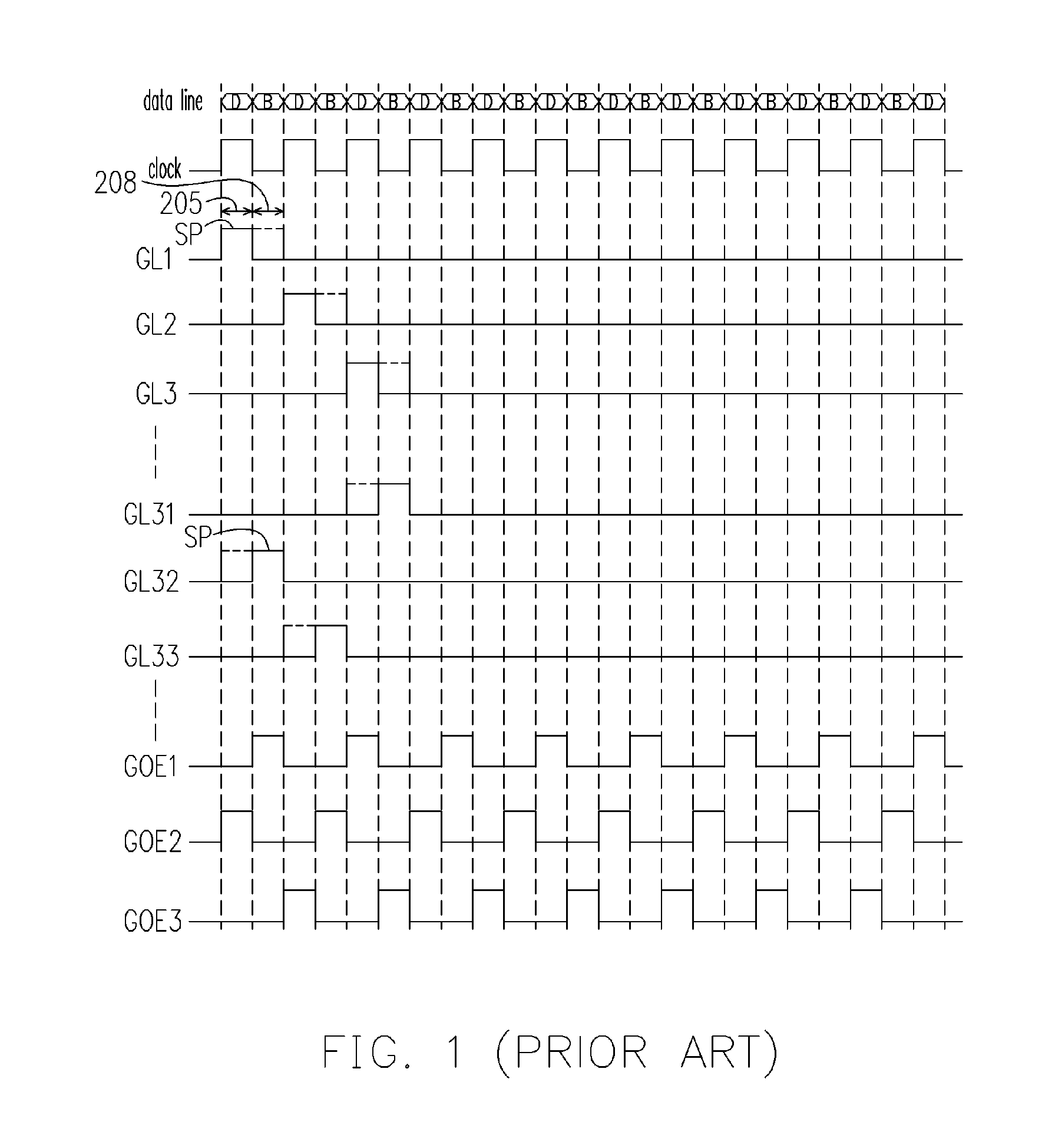
[0006]An object of the present invention is to provide an apparatus for driving a liquid crystal display (LCD), wherein a plurality of scan pulse signals having the same scan pulse period are utilized, combined with a plurality of output enable signals, thus achieving the object of black insertion, and thereby reducing the edge blur and improving display quality.
[0007]Another object of the present invention is to provide a method for driving an LCD, wherein the output enable signals are used to control the data writing timing and gray level writing timing in the scan pulse signal, such that the pixel has a longer charge time, and the object of black insertion can be achieved, thereby reducing the edge blur and improving display quality.
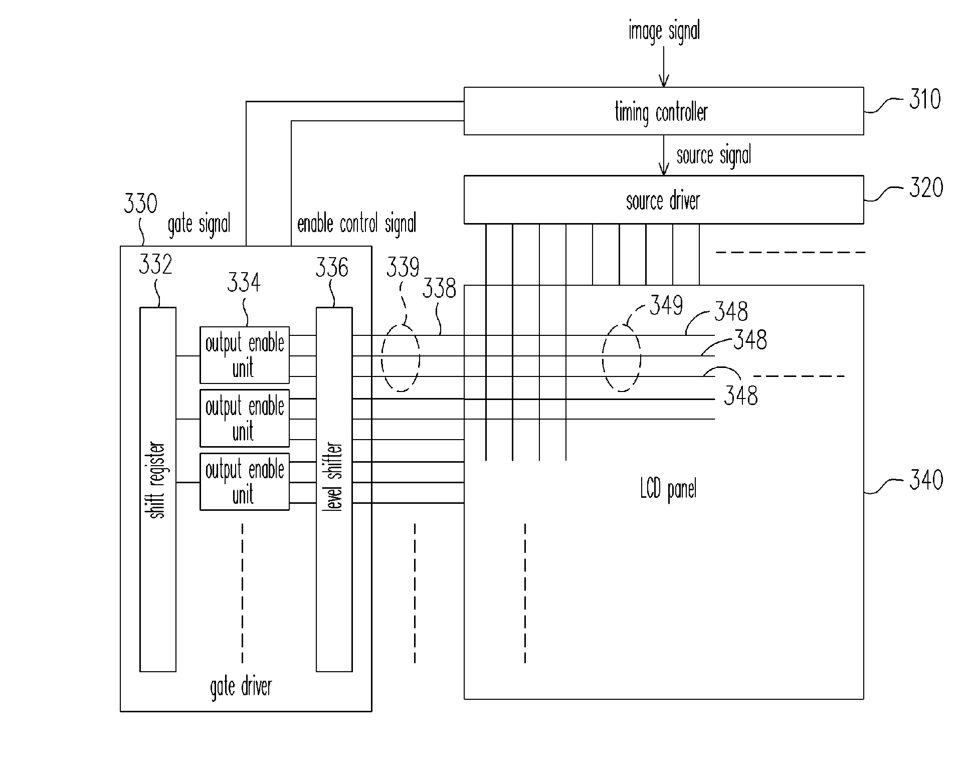
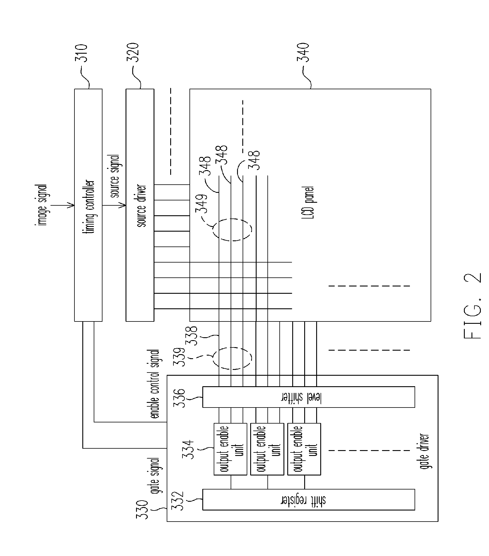
[0009]The gate driver, electrically connected to the timing controller, provides a plurality of scan pulse signals having a same scan pulse period according to the gate signal, and generates a plurality of output enable signals according to the enable control signal. The scan pulse signals are respectively enabled by the output enable signals and each scan pulse signal has one of a data writing period and a gray level writing period during the scan pulse period. During the data writing period, only one of the gate lines is turned on at a point in time by the scan pulse signal, and pixels, corresponding to the gate line which has been turned on, receive the data signal output by the source driver. During the gray level writing period, one of the gate line groups is turned on by the scan pulse signal, and pixels, corresponding to the gate line group which has been turned on, receive the gray level signal output by the source driver. Thus, the data signal is written by one gate line each time, and the gray level signal is written by gate lines (or a gate line group) each time simultaneously. Accordingly, the writing time for pixel can be increased, and the operating frequency for the gate driver can be reduced.
[0014]In the present invention, the scan pulse signals having the same scan pulse period are employed in combination with the output enable signals to control the data writing period and the gray level writing period of the signals outputted by the gate driver, thus the number of shift registers is greatly reduced, black insertion is achieved with a relatively low operating frequency, the edge blur of displaying moving images is diminished, and the charge time of pixels is maintained longer, thereby display quality is improved.

Problems solved by technology

However, since LCDs are of the hold-type light emitting mode and the response speed of the liquid crystal is slow, the problem of edge blur of the viewed images often occurs due to the integration effect of the human eye when the user watches moving images displayed by an LCD.
In this way, the edge blur can be reduced, but the operating frequency for the source driver must be increased, thus increasing the circuit complexity of the source driver; and meanwhile, the charge time for the liquid crystal pixels is shortened, thus affecting the display quality.

Method used


Image

  • Apparatus for driving liquid crystal display and method thereof
  • Apparatus for driving liquid crystal display and method thereof
  • Apparatus for driving liquid crystal display and method thereof

Examples


Embodiment Construction

[0021]Reference will now be made in detail to the present preferred embodiments of the invention, examples of which are illustrated in the accompanying drawings. Wherever possible, the same reference numbers are used in the drawings and the description to refer to the same or like parts.

[0022]To reduce the edge blur of the liquid crystal display (LCD) when displaying moving images, in an embodiment of the present invention, a plurality of scan pulse signals having the same scan pulse period are generated by the gate driver, combined with a plurality of output enable signals, so as to turn on a plurality of gate lines and input gray level signals such as black data, thus reducing the edge blur of the LCD while maintaining the pixel charge time as the conventional art. Meanwhile, with the architecture of the present invention, the operating frequency of the gate circuit and the complexity of the circuit can also be reduced.

[0023]Referring to FIG. 2, it is a block diagram of an apparat...


PUM


Abstract

An apparatus for driving a liquid crystal display (LCD) includes a timing controller, a source driver and a gate driver. A panel of the LCD includes gate line groups, and each of the gate line groups includes gate lines. Scan pulse signals having a same scan pulse period and output enable signals are generated by the gate driver. The scan pulse signals are respectively enabled by the output enable signals and each of the scan pulse signal has one of a data writing period and a gray level writing period during the scan pulse period. During the data writing period, only one of the gate lines is turned on at a point in time by the scan pulse signals. During the gate level writing period, one of the gate line groups is turned on by the scan pulse signals. Thus, the edge blur of displaying moving images is eliminated.

Description

BACKGROUND OF THE INVENTION[0001]1. Field of Invention[0002]The present invention relates to an apparatus for driving a flat panel display, more particularly to an apparatus for driving a liquid crystal display (LCD) and the method thereof for improving display quality by simultaneously turning on a plurality of gate lines and inserting black data.[0003]2. Description of Related Art[0004]Among consumer electronic devices, liquid crystal displays (LCDs) provide entertainment and real-time images, etc., thus, they usually display moving images, especially for LCD televisions. However, since LCDs are of the hold-type light emitting mode and the response speed of the liquid crystal is slow, the problem of edge blur of the viewed images often occurs due to the integration effect of the human eye when the user watches moving images displayed by an LCD.[0005]In the conventional art, the methods for improving the display quality of moving images mainly include overdrive and black insertion....

Claims


Application Information

Patent Timeline
IPC IPC(8): G09G3/36
CPCG09G3/3677G09G2310/0208G09G2320/0261G09G2320/0252G09G2310/061
Inventor CHENG, JUNG-CHIEHWU, CHIH-LIANG
Owner CHUNGHWA PICTURE TUBES LTD
Learn More