
Resonant cavity optoelectronic device with suppressed parasitic modes

a technology of parasitic modes and optoelectronic devices, which is applied in the field of ultrahigh-speed optoelectronic devices, can solve the problems and achieve the effect of reducing the effect of parasitic modes on the device performance and high reflectivity

Inactive Publication Date: 2007-12-20
CONNECTOR OPTICS
View PDF5 Cites 11 Cited by
  • Summary
  • Abstract
  • Description
  • Claims
  • Application Information

AI Technical Summary

Benefits of technology

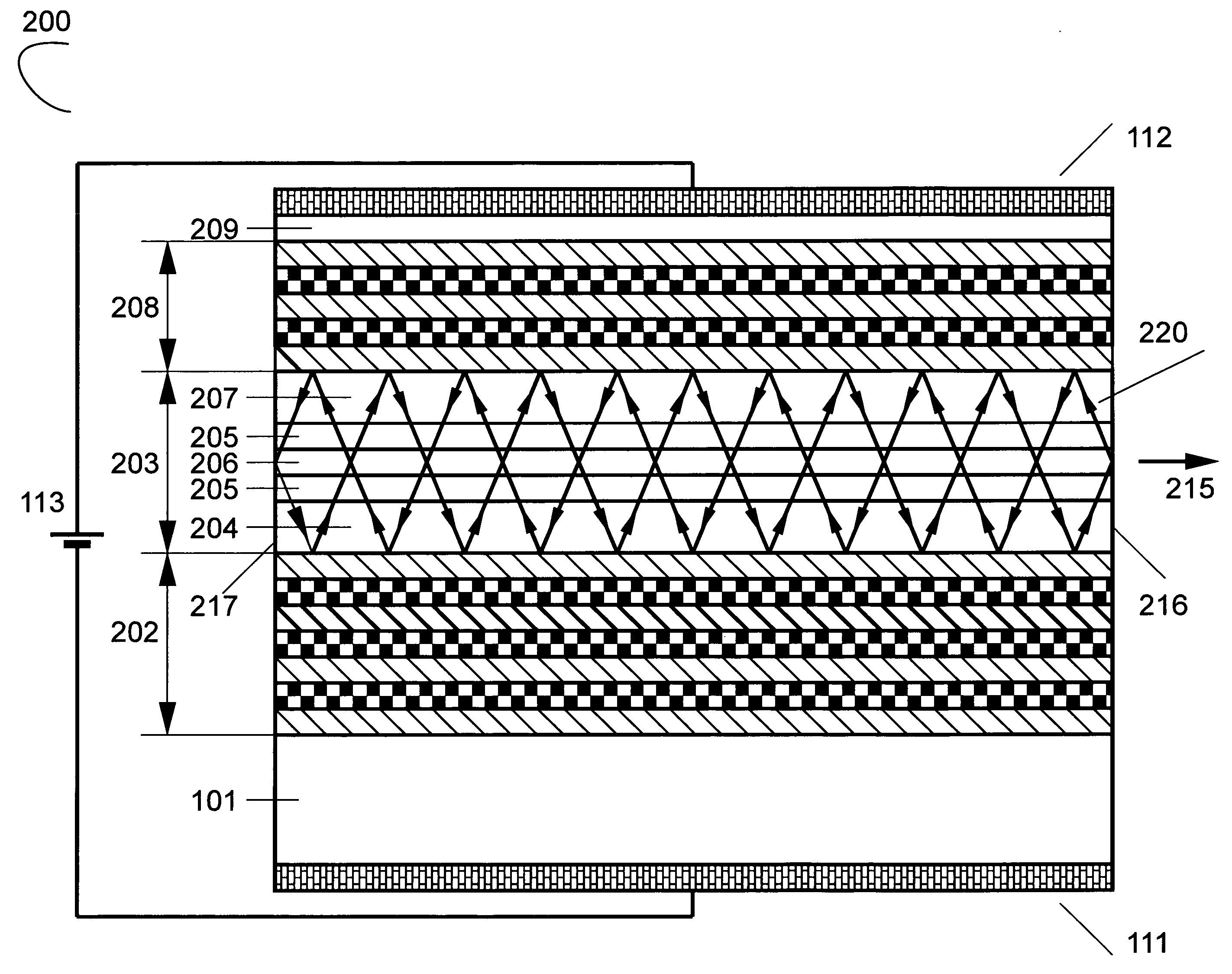
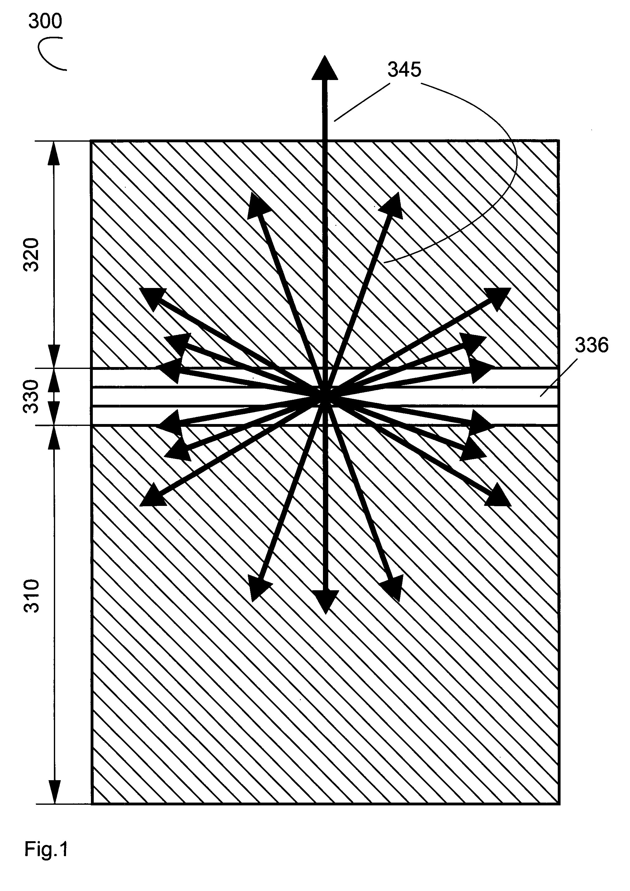
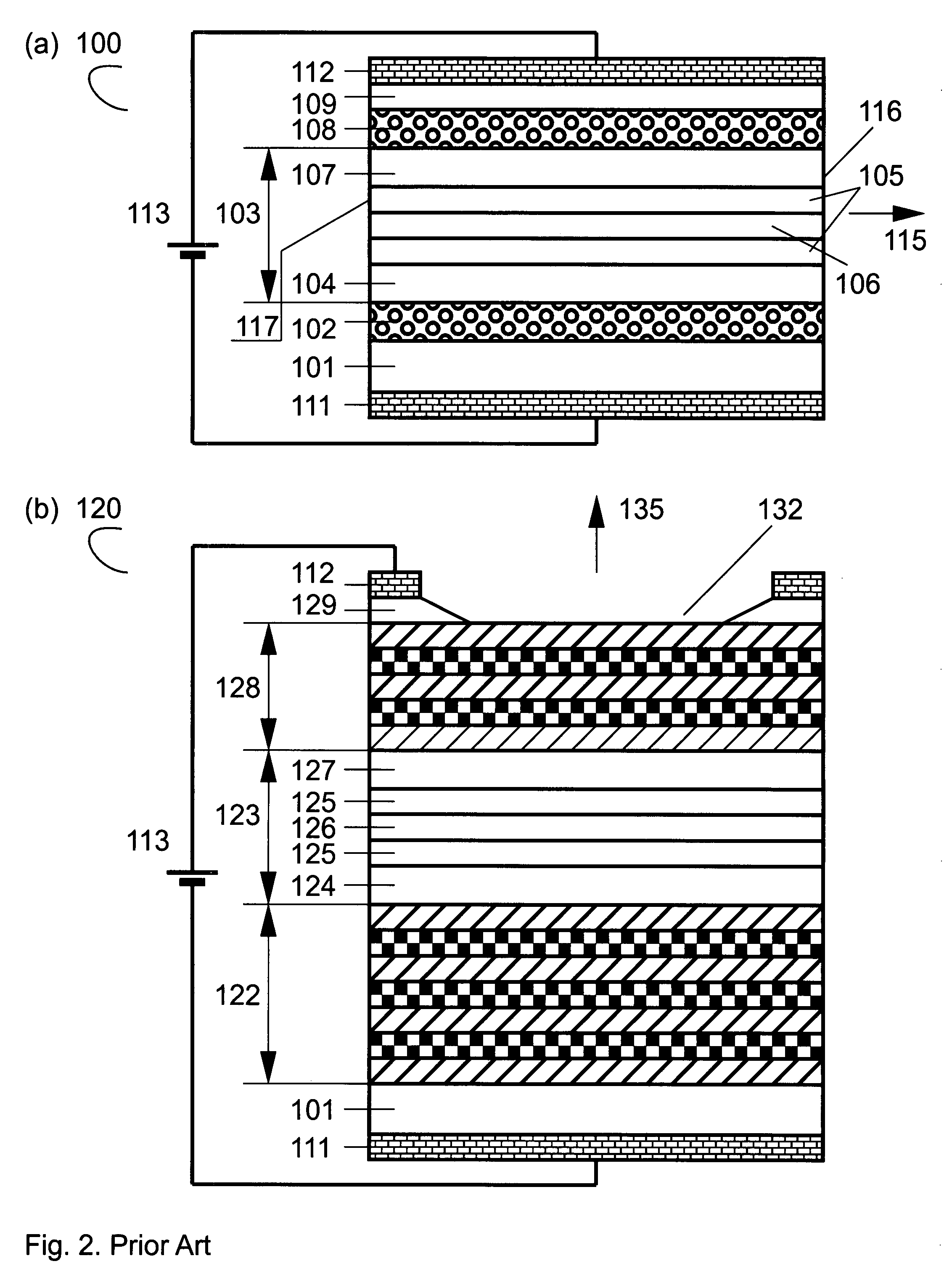
[0037]A optoelectronic device is disclosed containing at least one multilayer interference reflector, having at least two periodicities in the refractive index. At least one of the periodicities, or quasi-periodicities, prohibits the light emission in a range of angles tilted with respect to the intentionally selected direction, for example, in the direction perpendicular to the layer planes, preventing the emission of light in the optical modes propagating in a certain interval of angles, dangerous for the device, and thus reducing the effect of parasitic modes on the device performance. A light generating element emitting light in a certain wavelength range is preferably introduced in one of the layers. The light is then channeled into the required angle range. The device can additionally contain a cavity. A second periodicity of the refractive index is preferably selected to ensure a high reflectivity in the vertical direction enabling advanced vertical cavity surface-emitting lasers.

Problems solved by technology

At least one of the periodicities, or quasi-periodicities, prohibits the light emission in a range of angles tilted with respect to the intentionally selected direction, for example, in the direction perpendicular to the layer planes, preventing the emission of light in the optical modes propagating in a certain interval of angles, dangerous for the device, and thus reducing the effect of parasitic modes on the device performance.

Method used


Image

  • Resonant cavity optoelectronic device with suppressed parasitic modes
  • Resonant cavity optoelectronic device with suppressed parasitic modes
  • Resonant cavity optoelectronic device with suppressed parasitic modes

Examples


Embodiment Construction

[0067]The present invention provides a way to improve performance of light-emitting diodes, laser diodes, optical amplifiers and photodetectors by suppressing the undesirable radiative modes. The directionality, the efficiency and the modulation speed of the devices can be improved.

[0068]The basic approach to improve directionality at a certain wavelength is to place the source of the light in a multilayer epitaxial structure. FIG. 4(a) shows schematically a semiconductor structure (400), wherein an optical oscillator (460), emitting light having a certain photon energy which corresponds to the wavelength of light in the vacuum λ0, is inserted into a medium (450) with modulated refractive index, i.e. into a multilayer structure. The multilayer structure (450) is selected such that light in some directions (435) exits the crystal with high probability, whereas light does not come out in some other directions (465).

[0069]FIGS. 4(b) through 4(f) illustrate the possibility to forbid tra...


PUM


Abstract

A optoelectronic device is disclosed containing at least one multilayer interference reflector, having at least two periodicities in the refractive index. At least one of the periodicities, or quasi-periodicities, prohibits the light emission in a range of angles tilted with respect to the intentionally selected direction, for example, in the direction perpendicular to the layer planes, preventing the emission of light in the optical modes propagating in a certain interval of angles, dangerous for the device, and thus reducing the effect of parasitic modes on the device performance. A light generating element emitting light in a certain wavelength range is preferably introduced in one of the layers. The light is then channeled into the required angle range. The device can additionally contain a cavity. A second periodicity of the refractive index is preferably selected to ensure a high reflectivity in the vertical direction enabling advanced vertical cavity surface-emitting lasers.In other embodiments a double periodicity is selected to ensure a high reflectivity of light in a direction tilted with respect to the vertical direction. An optoelectronic device having a multilayer interference reflector with two periodicities can operate as a light-emitting diode, a superluminescence light-emitting diode, a laser diode, a single photon emitter, or an emitter of entangled photons.

Description

REFERENCE TO RELATED APPLICATIONS[0001]This application claims an invention which was disclosed in Provisional Application No. 60 / 814,054, filed Jun. 16, 2006, entitled “RESONANT CAVITY OPTOELECTRONIC DEVICE WITH SUPPRESSED PARASITIC MODES”. The benefit under 35 USC § 119(e) of the United States provisional application is hereby claimed, and the aforementioned application is hereby incorporated herein by reference.BACKGROUND OF THE INVENTION[0002]1. Field of the Invention[0003]The invention pertains to the field of semiconductor devices. More particularly, the invention pertains to ultrahigh-speed optoelectronic devices, such as light-emitting diodes and laser diodes[0004]2. Description of Related Art[0005]Optoelectronic devices are broadly applied in modern datacommunication, telecommunication, optical storage, display and lighting systems. These devices usually require directional light extraction from the device with power concentration is a certain angle, as characterized by bri...

Claims


Application Information

Patent Timeline
Patent Type & Authority Applications(United States)
IPC IPC(8): H01L31/00
CPCH01L31/0232H01L33/0045H01L33/105H01S5/18313H01S2301/18H01S5/18327H01S5/1833H01S5/2004H01S5/2027H01S5/18316
Inventor SHUCHUKIN, VITALYLEDENTSOV, NIKOLAI
Owner CONNECTOR OPTICS
Learn More