
Method for Connecting a Sheet Metal Component, Such as a Pipe, to a Cast Metal Component, Such as a Housing Port, in Particular for an Exhaust System

Active Publication Date: 2007-12-20
BORG WARNER INC
View PDF7 Cites 27 Cited by
  • Summary
  • Abstract
  • Description
  • Claims
  • Application Information

AI Technical Summary

Benefits of technology

[0019] In one embodiment, there may be provision for at least those regions of the at least one sheet metal component and of the housing port which are to be welded to be thermally controlled to a suitable processing temperature before welding. By virtue of this additional measure, it is possible to counteract too high a temperature gradient at those regions of the at least one sheet metal component and of the housing port which are to be welded, that is to say where the weld seam occurs. Thermal inhomogeneities which cause cracks are thus avoided along the weld seam occurring during welding. These regions are either to be preheated or to be cooled, depending on an existing initial temperature. Within the framework of a large-scale manufacturing process, there is the possibility of welding components to be welded together immediately after a preceding manufacturing step in which at least one of the components has been heated. In this case, it is possible to control thermally at least one component to be welded to the processing temperature within an annealing furnace.
[0033] Thermal expansion of the inner pipe or gas-carrying pipe, highly heated during the operation of the exhaust system, of the airgap-insulated exhaust manifold is compensated in a simple way due to the sliding fit between the gas-carrying pipe and the turbocharger. The gas-carrying pipe can in this case expand into the turbocharger, without forces in this case being transmitted, that is to say a free expansion of the gas-carrying or inner pipe in relation to the inflow gas duct of the turbocharger is possible.

Problems solved by technology

However, no direct connection between the exhaust manifold and the engine or, as required, a turbocharger is made as a result of this measure.

Method used


Image

  • Method for Connecting a Sheet Metal Component, Such as a Pipe, to a Cast Metal Component, Such as a Housing Port, in Particular for an Exhaust System
  • Method for Connecting a Sheet Metal Component, Such as a Pipe, to a Cast Metal Component, Such as a Housing Port, in Particular for an Exhaust System

Examples


Embodiment Construction

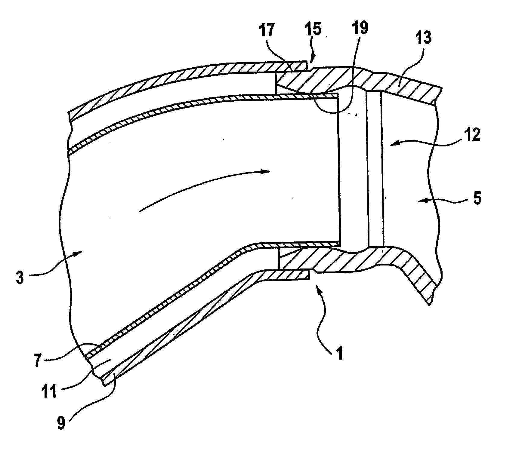
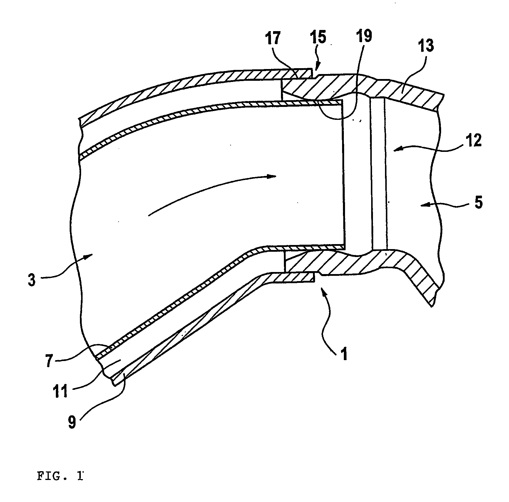
[0040] Accordingly, in the present case, the exhaust manifold 3 is designed as an airgap-insulated exhaust manifold 3. The housing 13 of the turbocharger 5 is manufactured from cast metal.

[0041] To provide, according to the invention, the connection 1 according to the invention between the exhaust manifold 3 and the turbocharger 5, there is provision for a cylindrical integrally formed portion 15 to be integrally formed in the region of a port 12 of the housing 13, that is to say the inflow gas duct of the turbocharger 5, on an outer wall.

[0042] When the double-walled exhaust manifold 3 is assembled with the housing 13 of the turbocharger 5, there is provision for first introducing the gas-carrying inner pipe 7 into the port 12, that is to say on an inner wall of the housing 13 of the turbocharger 5. The outer pipe 9 of the exhaust manifold 3 is pushed onto the housing 13 of the turbocharger 5 at the cylindrical integrally formed portion 15 on the inflow gas duct 12 of the housing...


PUM

PropertyMeasurementUnit
Temperatureaaaaaaaaaa

Abstract

In the method according to the invention for connecting a sheet metal component (3) to a component (5) consisting of cast metal, the sheet metal component (3) and the component (5) are welded to one another by means of a pulse-welding method. In particular, a sheet metal pipe (3) can thereby be welded to the port (12) of a housing (13) consisting of cast metal. This advantage may be utilized for an exhaust system with an exhaust manifold (3) and an exhaust assembly, such as a turbocharger (5).

Description

CROSS-REFERENCE TO RELATED APPLICATION [0001] This application is a national stage of PCT / EP2005 / 001873 filed Feb. 23, 2005 and based upon DE 10 2004 009 109.9 filed Feb. 25, 2004 under the International Convention.BACKGROUND OF THE INVENTION [0002] 1. Field of the Invention [0003] The invention relates to a method for connecting and to a connection of a sheet metal component to a component consisting of cast metal. The invention relates particularly to a method for connecting a pipe to a housing port, to a connection between a pipe and a housing port and to an exhaust system. [0004] Connections between pipes consisting of sheet metal and, for example, housing ports consisting of cast iron material are normally provided by means of flanges, including a seal. Only in this way is it possible to ensure a leakage-free transport of, for example, hot gases between the pipe and the housing port. [0005] In exhaust systems of motor vehicles, there is provision, according to previous concepts...

Claims


Application Information

Patent Timeline
IPC IPC(8): B23K26/32B23K9/028B23K9/23B23K26/00F01N13/08F01N13/10F01N13/18
CPCB23K9/0282B23K9/232B23K26/32B23K26/3206B23K26/3233F02B67/10B23K2201/04B23K2203/18F01N13/102F01N13/1805F01N2450/22B23K2201/006B23K26/323B23K2101/006B23K2101/04B23K2103/06B23K2103/18B23K2103/50
Inventor BIEN, WILFRIEDELFELDT, JAN PETERHALVES, MICHAELHUELSBERG, THOMASKLUSSMANN, UWEKUZI, HILDWINNUHN, HOLGERPUENJER, RALFREINHARDT, OLAYRIEWERT, DIRKRIGGERS, ALFREDSTERNAL, THORSTEN
Owner BORG WARNER INC
Learn More