Venting of on-board vehicle emissions treatment system with pressure assist

Inactive Publication Date: 2007-12-20
FORD GLOBAL TECH LLC
View PDF15 Cites 7 Cited by
  • Summary
  • Abstract
  • Description
  • Claims
  • Application Information

AI Technical Summary

Benefits of technology

[0007]A system and method for venting an on-board vehicle emissions treatment substance storage and distribution system that selectively dispenses an emissions treatment substance from a storage tank on the vehicle to an exhaust system of the vehicle include pressurizing the storage tank during engine operation and directly coupling the storage tank to the exhaust system upstream of an ammonia storage element to abate ammonia from the system or direct any escaping ammonia away from locations where people are more likely to be present.
[0008]Embodiments include an on-board emissions treatment system having a constant, passive coupling between a vehicle emissions treatment substance storage tank and a vehicle exhaust system so that exhaust pressure generated by operation of the engine increases pressure within the storage tank, which may assist the emissions treatment substance pump and distribution system and reduce vaporization of the emissions treatment substance in the space above the liquid within the tank. Exhaust pressure also inhibits or delays migration of vapors from the storage tank
[0009]The embodiments provide various advantages. For example, passive venting of the emissions substance treatment systems using urea through the exhaust system upstream of an ammonia storage device reduces or eliminates escaping ammonia. Any ammonia that escapes is diluted by exhaust gases during operation and redirected through the exhaust system, which is generally away from the refueling area and less likely to be objectionable to the operator or passengers. Passive venting does not require modifications to the vehicle control system and adds minimal cost / complexity to the vehicle. Coupling the emissions treatment substance storage tank to the exhaust passively pressurizes the storage tank to reduce vaporization while not using additional energy / power to operate a fan or other device to control venting. Increasing pressure in the coupling between the storage tank and the exhaust system delays or impedes migration of vapors from the storage tank. Similarly, venting the storage tank upstream of a catalyst allows vapors to be stored for some period of time depending on the vaporization rate, which also impedes or delays the escape of vapors from the system. Providing a continuous coupling between the storage tank and exhaust system allows venting of the storage tank even during long shut down periods. As such, the embodiments reduce or eliminate detectable odor associated with the release of untreated vapors from a vehicle emissions treatment system.

Problems solved by technology

Urea stored on-board the vehicle poses unique technical challenges.
For example, when subjected to temperatures common for underbody exhaust components, urea stored in the tank may begin to decompose and release ammonia to the air space above the liquid.
Similarly, venting the storage tank upstream of a catalyst allows vapors to be stored for some period of time depending on the vaporization rate, which also impedes or delays the escape of vapors from the system.

Method used


Image

  • Venting of on-board vehicle emissions treatment system with pressure assist
  • Venting of on-board vehicle emissions treatment system with pressure assist

Examples


Embodiment Construction

)

[0012]As those of ordinary skill in the art will understand, various features of the embodiments illustrated and described with reference to the Figure may be combined with other features to produce embodiments that are not explicitly illustrated or described. The combination of features illustrated provides a representative embodiment for typical applications. However, various combinations and modifications of the features consistent with the teachings of this disclosure may be desired for particular applications or implementations.

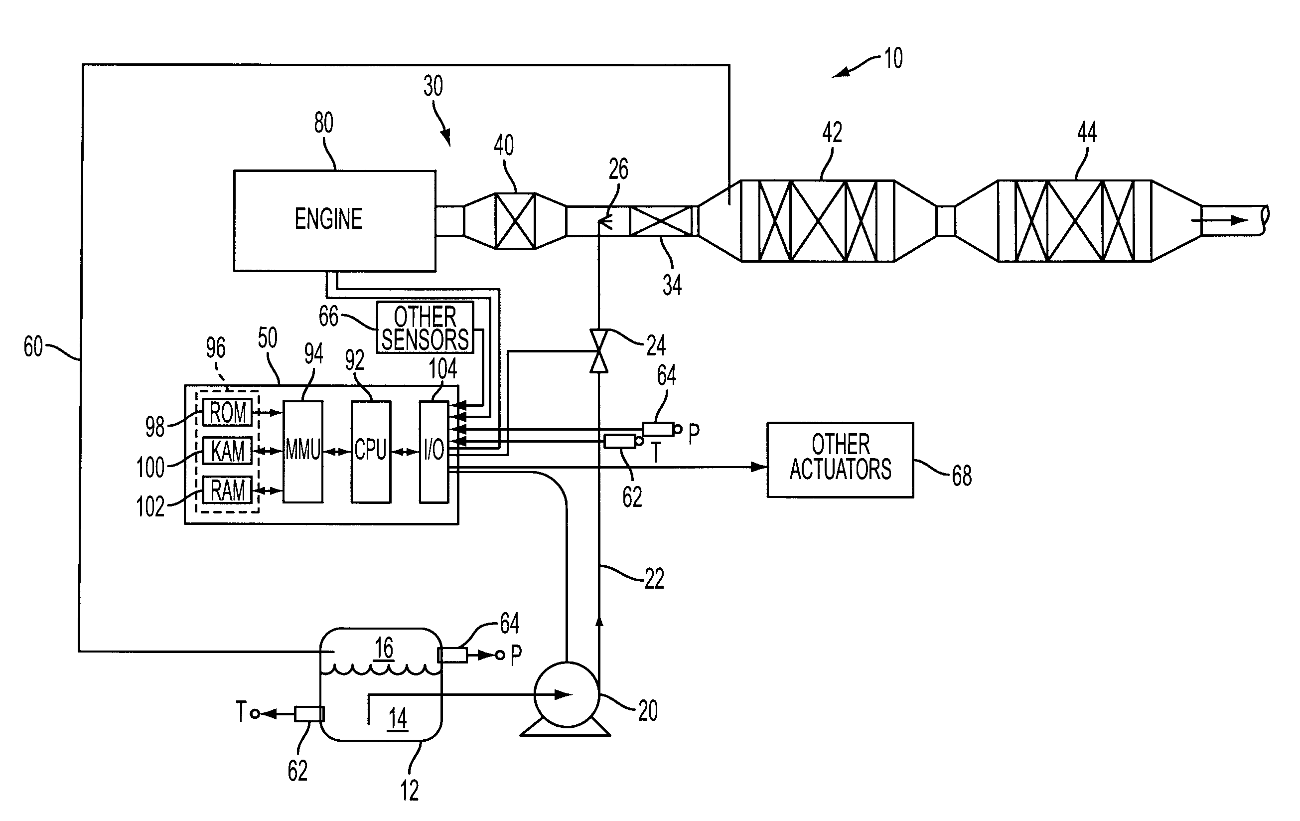
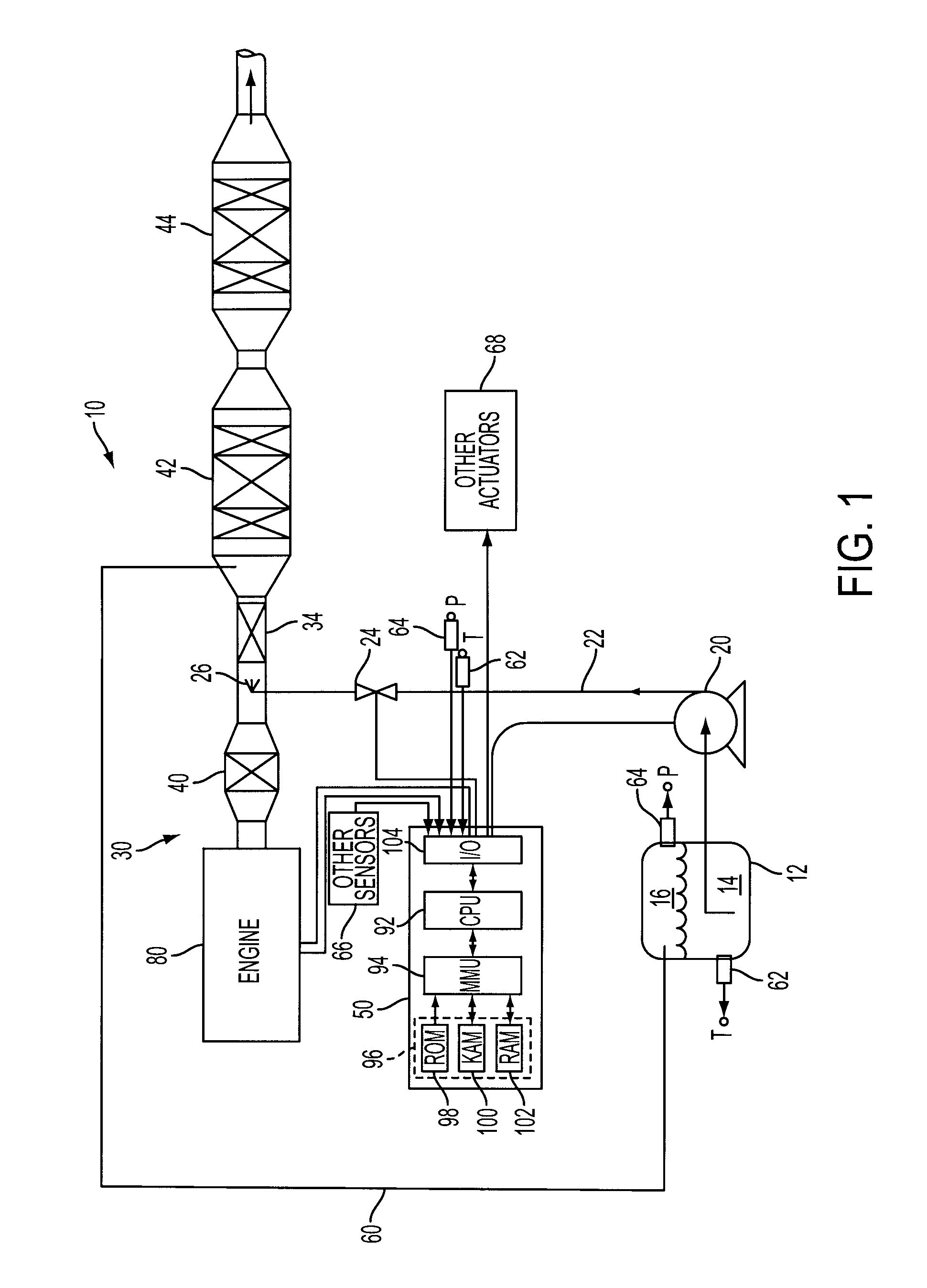
[0013]Referring now to FIG. 1, a block diagram illustrating one embodiment of a system or method for venting an on-board vehicle emissions treatment system with pressure assist is shown. System 10 includes an emissions treatment substance storage tank 12 mounted on a vehicle (not shown). Storage tank 12 may be used to store an emissions treatment substance 14, which may include, but is not limited to various reducing agents or reductants such as aqueous...


PUM


Abstract

A system and method for venting an on-board vehicle emissions treatment substance storage and distribution system that selectively dispenses an emissions treatment substance from a storage tank on the vehicle to an exhaust system of the vehicle include pressurizing the storage tank during engine operation and coupling the storage tank to the exhaust system upstream of an ammonia storage element to reduce and direct any escaping ammonia toward the rear of the vehicle away from a refueling location.

Description

BACKGROUND[0001]1. Technical Field.[0002]The present disclosure relates to systems and methods for venting an on-board emissions treatment system of a vehicle.[0003]2. Background Art.[0004]Various types of vehicle emission control systems introduce one or more substances directly or indirectly to the engine via the fuel supply, air / fuel intake, exhaust, or directly to an engine cylinder or emissions control device, such as a catalyst. For example, substances acting as reducing agents or reductants, such as aqueous urea or hydrocarbons (other than fuel) may be used in lean air / fuel ratio engine applications including diesel engines in combination with lean NOx catalysts (or selective catalytic reduction (SCR)) to treat nitrous oxide feedgas emissions. These substances generally require a storage and distribution system separate from the primary fuel storage and distribution system.[0005]Liquid urea selective catalytic reduction (SCR) is a method of mobile exhaust aftertreatment parti...

Claims


Application Information

Patent Timeline
IPC IPC(8): F02M25/06F01N5/00F01N3/00
CPCF01N3/2066Y02T10/24F01N2610/06F01N2610/02Y02A50/20Y02T10/12B01D53/94F01N3/206
Inventor DAWSON, KENTSHAIKH, FURQANLEVIN, MICHAELCOOK, DAVIDKABAT, DANIEL
Owner FORD GLOBAL TECH LLC
Why Eureka
Try Eureka