Adaptable Network Service Access Through Dynamic Request Routing

a network service and dynamic request technology, applied in the field of adaptable network service access through dynamic request routing, can solve the problems of home sdm change for a subscriber, network complexity can be a problem, and the slf approach used in the present ims standard suffers from certain drawbacks, so as to reduce the number of discrete elements and reduce the complexity of the network

Active Publication Date: 2007-12-13
APPLE INC
View PDF4 Cites 18 Cited by
  • Summary
  • Abstract
  • Description
  • Claims
  • Application Information

AI Technical Summary

Benefits of technology

[0019] In one embodiment, the SLF is co-located with one of the subscriber data servers. Advantageously, co-location provides a reduction in network complexity by reducing the number of discrete elements. Also, since a separate, discrete SLF requires a subset of the subscription data maintained across all partitions (eg a mapping from user identity to subscriber data server) it will require (geo) synchronization and redundancy mechanisms separate and in addition to those already operating in the subscriber data management service. Through co-location, the (geo) synchronization and redundancy mechanisms required for the subscriber data service may be re-used for the subscriber location functions. In another embodiment, the SLF is a stand alone mechanism to the plurality of subscriber data servers.

Problems solved by technology

The SLF approach used in present IMS standards suffers from certain drawbacks.
Network complexity can be a problem since the SLF must appear as a distinct service to the SDM and each network element must maintain separate Diameter sessions to the SLF and the SDM
Handling a change of the home SDM for a subscriber (as a result of a site failure through disaster or a matter of administrative reorganization) can also be a problem.
This is a significant processing overhead for each subscriber that is “moved” from one SDM to another and for large subscriber moves a very high processing overhead with impact on latency as well.
Also, using the re-direct routing service forces network elements to be capable of handling Diameter re-direct replies which adds complexity to the network elements.
Moreover, increased processing overhead is incurred at the network element as a result of redirection.

Method used


Image

  • Adaptable Network Service Access Through Dynamic Request Routing
  • Adaptable Network Service Access Through Dynamic Request Routing
  • Adaptable Network Service Access Through Dynamic Request Routing

Examples


Embodiment Construction

[0030] Embodiments of the present invention are described below by way of example only. These examples represent the best ways of putting the invention into practice that are currently known to the Applicant although they are not the only ways in which this could be achieved.

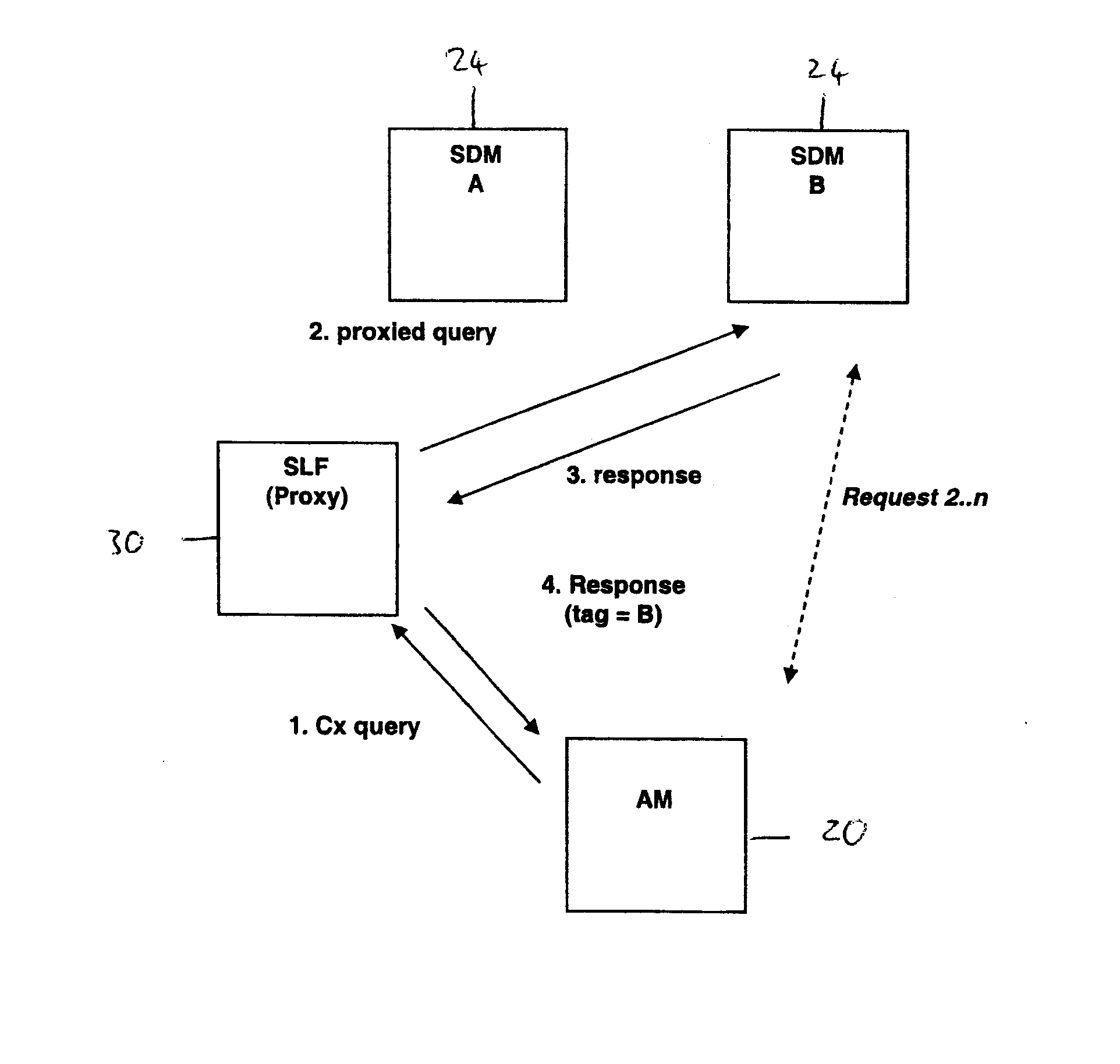
[0031]FIG. 3 shows the placement options for a proxy SLF 30 for each geographic region according to the present invention. There are four options: 1) network level placement; 2) co-located with the SDM; 3) regional level placement and 4) co-located with each network element.

[0032] Placement needs to address two key issues. Network element query latency and data management complexity associated with keeping SLF data in sync with SDM data distribution.

[0033] The preferred option is to co-locate the SLF with the SDM (option 2) for the following reasons. Co-locating the SLF with the SDM enables the SLF to use the same data management infrastructure, sharing data, robustness and redundancy mechanisms used by other...


PUM


Abstract

In an Internet Protocol Multimedia Subsystem (IMS) network in which multiple subscriber data servers are deployed with partitioned subscription data for users, a subscriber location function (SLF) is used to proxy queries to a subscriber data server (such as an HSS) in which subscription data for a user can be found. The SLF receives a query for the subscriber data server, looks up the address of appropriate subscriber data server and proxies the query to the appropriate subscriber data server. Preferably, the SLF is co-located with a subscriber data server.

Description

FIELD OF THE INVENTION [0001] The present invention relates to methods of, systems for, computer programs for and apparatus for routing subscriber data queries in a communications network using the Internet Protocol (IP) Multimedia Subsystem (IMS). More particularly, the present invention relates to methods of, systems for, computer programs for and apparatus for routing subscriber data queries in a communications network using the IMS in which a subscriber data (for example subscriber data stored in a Home Subscriber Server (HSS)) is partitioned over several different subscriber data servers or functions. BACKGROUND TO THE INVENTION [0002] The IMS is an architecture for enabling the provision of IP based multimedia services in 3G and subsequent mobile and converged fixed / mobile communications networks. Features of IMS are being standardized under the 3rd Generation Partnership Programme (3GPP) and 3GPP2. Various network elements in the IMS architecture will now be described by way ...

Claims


Application Information

Patent Timeline
Patent Type & Authority Applications(United States)
IPC IPC(8): G06F15/16
CPCH04L29/12132H04L29/12188H04L29/1282H04L61/1552H04W8/183H04L61/6013H04L65/1016H04L65/1073H04L61/1588H04L61/4552H04L61/4588H04L61/59
Inventor PRICE, DAVIDDARBYSHIRE, ALANKAURA, RICKY
Owner APPLE INC
Why Eureka
Try Eureka