Microdialysis probe
a microdialysis and probe technology, applied in the field of microdialysis probes, can solve the problems of limited use of currently-existing devices, local muscle pain and tenderness, and little knowledge about biochemical differences in the local tissue milieu,
- Summary
- Abstract
- Description
- Claims
- Application Information
AI Technical Summary
Problems solved by technology
Method used
Image


Examples
example 1
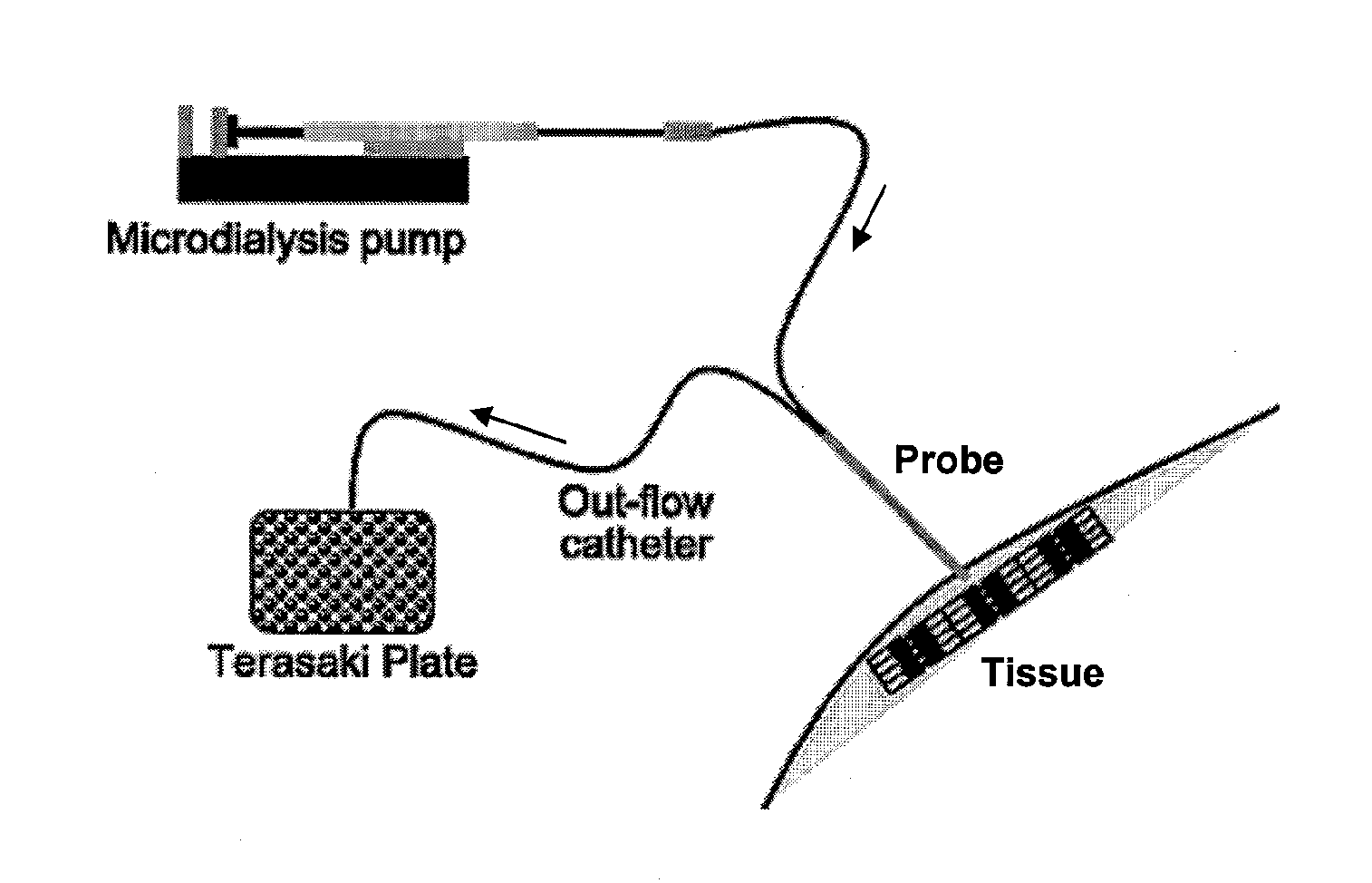
[0058] A prototype needle microdialysis system was developed comprising a hollow small-bore needle equipped with a microdialysis membrane, standard microdialysis connection tubing, a microdialysis perfusion pump, and a sample collection device. The system was designed to continuously collect samples, e.g., from the internal tissue milieu of human muscle, and could be used as a surrogate acupuncture needle during routine treatment of MTrPs (FIGS. 1 and 3).
[0059] Needle construction. The needle was constructed from a 2.5-in section of 30-gauge commercially available stainless steel hypodermic tubing (Small Parts, Miami Lakes, Fla.). One end was carefully ground internally and externally before being polished to a cone to minimize tissue injury in a similar manner to that of a standard Japanese-style acupuncture needle.
[0060] Membrane. An 85-μm-diameter disk was cut from a 105-μm-thick sheet of cellulose ester semi-permeable membrane (Spectrum Laboratories, Rancho Dom...
example 2
Sample Analysis
[0064] Sample analysis. Due to the extremely small volumes collected from the microdialysis system (˜0.5 μL), analysis of each sample was performed in the Ultramicro Analytical Immunochemistry Resource (UAIR) by immunoaffinity capillary electrophoresis (ICE) and capillary electrochromatography (CEC). Measurement pH was made with a modified microcombination electrode in combination with an Orion model 370 pH meter (Thermo Electron, Woburn, Mass.) capable of making pH measurements in ˜0.2 μL of fluid. Samples were examined within 4 h of collection, and pH measurements were made immediately on arrival in the UAIR. Each sample was recovered from the Terasaki plate, measured for volume, and stored at −80° C. until analyte analysis by ICE and CEC. The major advantages of ICE and CEC are the extremely small sample volumes required for analysis (˜50 nl or 0.05 μL) and their high detection sensitivities (˜0.5 pg / mL). An added advantage of ICE is that the employment of an anti...
example 3
Results and Characterization of System Calibration
[0067] Recovery of the molecular mass standards demonstrated that the largest standard to be reliably recovered was 75,000 Da, with maximum recovery efficiency (86% in both the fluid samples and the tissue deposits. Collected samples were examined for volume variation and the presence of air bubbles. The mean volume collected per patient was 0.5±0.003 μl and the presence of air bubbles was undetectable in any of the patient samples.
[0068] Table 1, below, depicts results from the recovery of analyte standards from saline, human muscle extract, and isolated rat trapezius muscle in-situ deposition.
TABLE 1Percentage Recovery atDifferent Flow RatesAnalyteMedium1 μl / min2 μl / minBradykininSaline85.6 ± 6.294.6 ± 3.6Tissue extract86.6 ± 8.893.8 ± 5.4In situ88.4 ± 7.295.0 ± 5.8CGRPSaline95.5 ± 3.897.6 ± 2.1Tissue extract94.9 ± 4.296.8 ± 3.5In situ93.7 ± 5.596.2 ± 3.2SPSaline95.6 ± 4.298.2 ± 1.2Tissue extract94.9 ± 4.197.2 ± 2.2In situ92.1 ±...
PUM
 Abstract
Description
Claims
Application Information
 - R&D
- Intellectual Property
- Life Sciences
- Materials
- Tech Scout
- Unparalleled Data Quality
- Higher Quality Content
- 60% Fewer Hallucinations
Browse by: Latest US Patents, China's latest patents, Technical Efficacy Thesaurus, Application Domain, Technology Topic, Popular Technical Reports.
© 2025 PatSnap. All rights reserved.Legal|Privacy policy|Modern Slavery Act Transparency Statement|Sitemap|About US| Contact US: help@patsnap.com