Eureka AIR delivers breakthrough ideas for toughest innovation challenges, trusted by R&D personnel around the world.

Non aqueous gel technology

a technology of non-aqueous gel and wellbore, which is applied in the direction of wellbore/well accessories, sealing/packing, chemistry apparatus and processes, etc., can solve the problems of loss of circulation, loss of well control, loss or decrease of production

Inactive Publication Date: 2007-12-13
MI
View PDF11 Cites 31 Cited by
  • Summary
  • Abstract
  • Description
  • Claims
  • Application Information

AI Technical Summary

Problems solved by technology

Lost circulation is a recurring drilling problem, characterized by loss of drilling mud into downhole formations that are fractured, highly permeable, porous, cavernous, or vugular.
Other problems encountered while drilling and producing oil and gas include stuck pipe, hole collapse, loss of well control, and loss of or decreased production.
Induced mud losses may also occur when the mud weight, required for well control and to maintain a stable wellbore, exceeds the fracture resistance of the formations.
A particularly challenging situation arises in depleted reservoirs, in which the drop in pore pressure weakens hydrocarbon-bearing rocks, but neighboring or inter-bedded low permeability rocks, such as shales, maintain their pore pressure.
This can make the drilling of certain depleted zones impossible because the mud weight required to support the shale exceeds the fracture resistance of the sands and silts.
The problem associated with producing from a well in this manner relates to the control of the flow of fluids from the well and to the management of the reservoir.
The production of water near the heel reduces the overall production from the well.
Later, oil-based muds are substituted as the well gets deeper and reaches the limit of water-based muds due to limitations such as lubricity and well bore stabilization.
There is, however, a dearth of methods using non-aqueous gels which are compatible with oil-based muds.

Method used


Image

  • Non aqueous gel technology
  • Non aqueous gel technology
  • Non aqueous gel technology

Examples


example 1

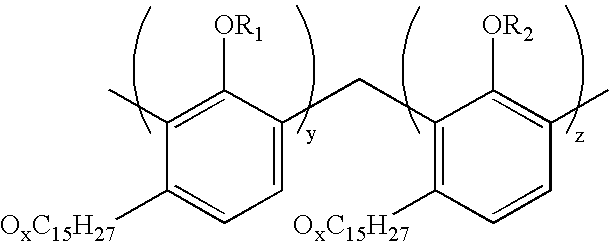
[0057]A gel was synthesized by mixing Cardolite® NC-547 and Jeffamine® T-5000 in a 1:1 ratio in mineral oil and heated to 70° C. After heating for 16 hours, a firm gel is formed.

TABLE 1Effect of Added Tertiary Amine (Triisopropanolamine)HardnessLipophilicAmineTertiaryObservs.Observs. @aftermonomerBase OilcrosslinkerAmine@ 70° C.70° C.agingEpoxy Resin;83%8%1%Liq @ 6 hElastic Gel 85 psi8%16 hEpoxy Resin;82%8%2%Liq @ 6 hElastic Gel165 psi8%16 hEpoxy Resin;80%8%4%Liq @ 6 hElastic Gel218 psi8%16 h

EXAMPLE 2

[0058]The following non aqueous gel was formulated to illustrate the characteristics of an exemplary non aqueous gel:

TABLE 2MaterialFunctionAmountDF1Base Oil10 mL Cardolite NC 547Epoxy Gelling Agent2 mLJeffamine T5000Trifunctional amine Gelling Agent2 mLTriisopropanolamineTertiary amine hardening agent0.2 mL  

[0059]Cardolite® NC-547, Jeffamine® T-5000, Triisopropanolamine, and base oil are mixed with an equivalent concentration of the additives found in Table 3:

TABLE 3AdditiveDescriptio...

example 2

[0062]Table 5 details a non aqueous gel formulated to illustrate the viscosity of an exemplary gel formulation:

TABLE 5AdditiveAmountg or mIFunctionHDF190mlBase oilVERSAGEL2.3gOrganoclaySUPREMEJEFFAMINE T500045mlTrifunctional AminepolymerCARDOLITE45mlEpoxidised PolymerNC547ResinTriisopropanolamine0.3mlTertiary AminehardenerSTARCARB60gbridging solidFORDACAL 6041.2gbridging solidG-SEAL18.8gbridging solid

[0063]The components in Table 5 were mixed, and tested prior to gelling. The viscosity was measured using a Brookfield DV-II+ Viscometer using spindle LV2 at 0.3 rpm at 25° C. Table 6 details the typical viscosity ranges for the Brookfield DV-II+ Viscometer at 1, 2, and 3 minutes.

TABLE 6Viscosity @(cps)1 m11,3002 m12,3003 m13,500

[0064]Thereafter, a repeat test was conducted to verify the viscosity of the mixture at various rotational speeds. The viscosity of the mixture at 25° C. was determined using a LV1 spindle. The resulting viscosities are listed in Table 7.

TABLE 7Viscosity (cps)Ro...

example 3

[0065]The following formulation in Table 8 illustrates the viscosity of an exemplary gel formulation comprising 10.5 ppg of carbonate:

TABLE 8ProductSgWeightVolumeFunctionDiesel0.840113.82135.51Base oilVERSAGEL1.7004.502.65Organoclay ViscosifierSUPREMECARDOLITE0.90060.9867.75Epoxidised PolymerNC547ResinJEFFAMINE T50001.00367.9667.75Trifunctional AminepolymerTriisopropanolamine1.0104.564.52Tertiary AminehardenerSAFECARB 402.680119.0044.40bridging solidSAFECARB 2502.68020.007.46bridging solid(blend)SAFECARB 5002.68025.009.33bridging solid(blend)G-SEAL2.25025.0011.11bridging solid

[0066]The components listed in Table 8 were mixed and the viscosity was measured prior to the mixture gelling. The viscosity was measured using a Brookfield DV-II+ Viscometer with spindle LV1 at 0.3 rpm at 25° C. Table 9 details the resulting viscosity, measured at 1, 2, and 3 minutes.

TABLE 9Time1 m2 m3 mSpindle 1Off scale atOff scale atOff scale atlowest speedlowest speedlowest speedSpindle 3 @ 0.3 rpm21,00023...


PUM

PropertyMeasurementUnit
Temperatureaaaaaaaaaa
Pressureaaaaaaaaaa
Pressureaaaaaaaaaa

Abstract

A method of treating an earth formation that includes injecting at least one lipophilic monomer into the earthen formation; wherein the at least one lipophilic monomer is selected from epoxide-functionalized derivative of soybean oil linseed oil, rapeseed oil, cashew nut shell oil; perilla oil, tung oil, oiticia oil, safflower oil, poppy oil, hemp oil, cottonseed oil, sunflower oil, high-oleic triglycerides, triglycerides of euphorbia plants, peanut oil, olive oil, olive kernel oil, almond oil, kapok oil, hazelnut oil, apricot kernel oil, beechnut oil, lupine oil, maize oil, sesame oil, grapeseed oil, lallemantia oil, castor oil, herring oil, sardine oil, menhaden oil, whale oil, and tall oil, injecting at least one crosslinking agent into the earthen formation; wherein the at least one crosslinking agent comprises at least one primary amine; and allowing the lipophilic monomer and the crosslinking agent to react in the earth formation is disclosed.

Description

CROSS-REFERENCE TO RELATED APPLICATIONS[0001]This application claims priority under 35 U.S.C. § 119(e) to U.S. Provisional Patent Application No. 60 / 804,349, filed Jun. 9, 2006, the disclosure of which is incorporated herein by reference.BACKGROUND OF INVENTION[0002]1. Field of the Invention[0003]The present disclosure relates generally to methods for improving wellbore strength, and more particularly, to methods to consolidate and stabilize the wellbore.[0004]2. Background Art[0005]Lost circulation is a recurring drilling problem, characterized by loss of drilling mud into downhole formations that are fractured, highly permeable, porous, cavernous, or vugular. These earth formations can include shale, sands, gravel, shell beds, reef deposits, limestone, dolomite, and chalk, among others. Other problems encountered while drilling and producing oil and gas include stuck pipe, hole collapse, loss of well control, and loss of or decreased production.[0006]Induced mud losses may also oc...

Claims


Application Information

Patent Timeline
IPC IPC(8): C09K8/00
CPCC09K8/32C09K8/588C09K8/50C09K8/36
Inventor BALLARD, DAVID ANTONY
Owner MI
Why Eureka
Eureka Blog
Learn More