
Atomic force microscope technique for minimal tip damage

a technology of atomic force microscope and afm, which is applied in the direction of mechanical measurement arrangement, mechanical roughness/irregularity measurement, instruments, etc., can solve the problems of afm tip damage, loss of accuracy and precision, and abrupt and sharp phase signal reversal

Inactive Publication Date: 2007-12-06
APPLIED MATERIALS INC
View PDF8 Cites 17 Cited by
  • Summary
  • Abstract
  • Description
  • Claims
  • Application Information

AI Technical Summary

Benefits of technology

[0009]One embodiment of the invention provides a method of automatically detecting a setpoint useful in controlling a tip-to-sample distance of an atomic force microscope (AFM). The method generally consists of modulating the tip-to-sample distance of the AFM by adjusting a setpoint of a feedback mechanism of the AFM, monitoring a detector signal provided by a detector mechanism in order to detect an event indicative of an abrupt change or an approaching abrupt change in the detector signal, and using a setpoint corresponding to the detected event to subsequently control the AFM.
[0010]Another embodiment of the invention provides a method of automatically detecting a setpoint useful in controlling a tip-to-sample distance of an atomic force microscope (AFM). The method generally consists of adjusting a tip of the AFM relative to a sample to establish an initial tip-to-sample distance, enabling a feedback mechanism, reducing an amplitude setpoint of the feedback mechanism, thereby causing a reduction of the tip-to-sample distance, monitoring at least a phase signal provided by a detector, repeating the previous two steps until an abrupt change or approaching abrupt change in the phase signal provided by the detector is detected, and recording an amplitude setpoint corresponding to the detected change in the phase signal for subsequent use in operating the AFM.
[0011]Another embodiment of the invention provides for an atomic

Problems solved by technology

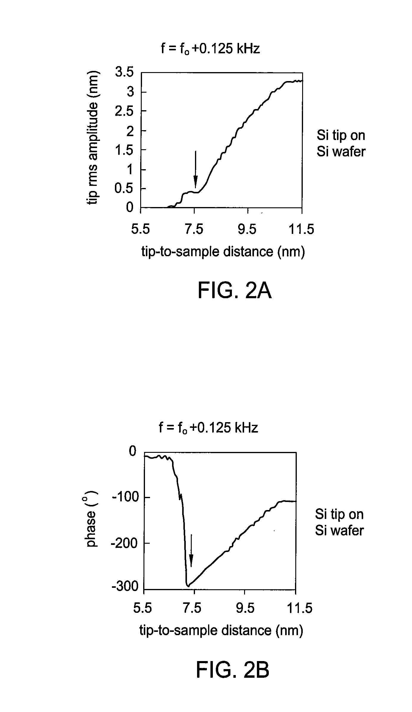
Further decrease of the tip-to-sample distance will cause intermittent hard contact between the tip and the sample surface along with an abrupt and sharp reversal of the phase signal.
Such hard contact usually causes AFM tip damage and the loss of accuracy and precision.
However, in this measurement, the tip is repeatedly rammed into the sample surface with no control at all and the tip will certainly be damaged during the measurement.
Due to tip damage, the critical setpoint measured may be grossly inaccurate.

Method used


Image

  • Atomic force microscope technique for minimal tip damage
  • Atomic force microscope technique for minimal tip damage
  • Atomic force microscope technique for minimal tip damage

Examples


Embodiment Construction

[0023]The present invention provides a means to determine and use a critical feedback setpoint with an atomic force microscope (AFM) in an effort to avoid tip damage and remain in non-contact attractive mode during use.

An Exemplary AFM System

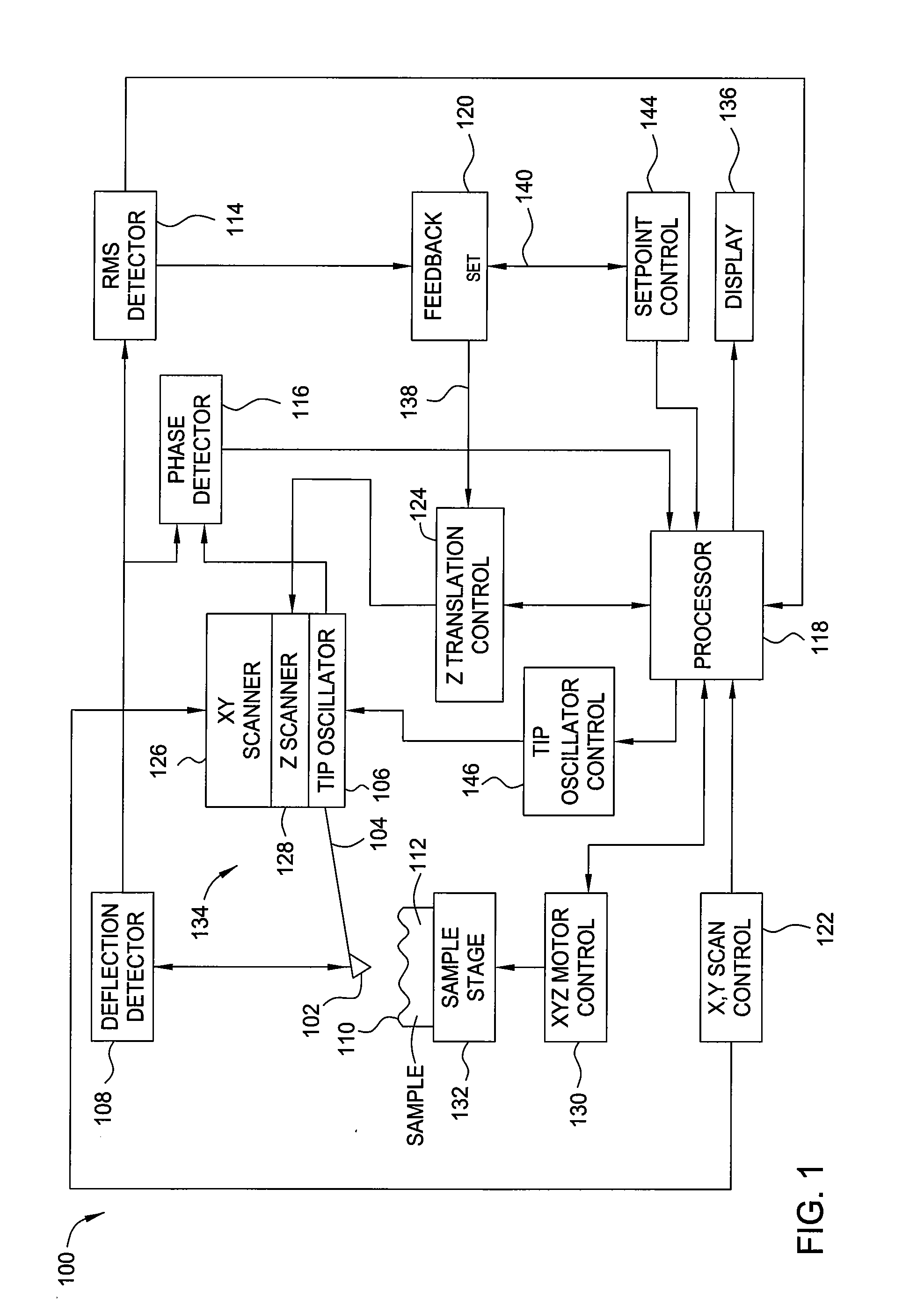
[0024]FIG. 1 is a simplified functional block diagram of an atomic force microscope 100 for dynamic mode operation including a probe / sample positioning apparatus and a feedback system using an amplitude feedback setpoint 140 in accordance with one embodiment of the present invention. A phase feedback setpoint (not shown) may be employed in other embodiments of the invention, although this description will focus primarily on an amplitude feedback setpoint 140 to maintain consistency and avoid confusion.

[0025]A probe tip 102 on the end of a cantilever 104 may be oscillated at a known free oscillation amplitude and frequency near the cantilever resonant frequency by a tip oscillator 106. The cantilever resonant frequency may be around 300 kHz, and ...


PUM


Abstract

Methods and apparatus for automatically determining a feedback setpoint for use in operating an atomic force microscope (AFM) are provided. The setpoint may be determined by modulating a feedback setpoint while monitoring for a change in a detector signal. In an effort to avoid tip damage and remain in non-contact, attractive mode during use, a setpoint just above a setpoint corresponding to a detected change in a parameter of the detector signal, such as an abrupt change in phase, may be used to operate the AFM.

Description

BACKGROUND OF THE INVENTION[0001]1. Field of the Invention[0002]Embodiments of the present invention generally relate to a method of using an atomic force microscope (AFM), and more particularly to a method of determining a feedback setpoint value for use in operating the AFM.[0003]2. Description of the Related Art[0004]The surface roughness and morphology of gate dielectrics and other semiconductor thin films are critical properties that need to be controlled to ensure integrated circuit device integrity and reliability. These properties can be measured by an atomic force microscope (AFM) operated in dynamic mode. In dynamic mode operation the AFM tip is oscillated near the cantilever resonance frequency with the oscillating amplitude and phase monitored by a detection mechanism and AFM electronics.[0005]As the AFM tip gradually approaches the sample surface, it will first enter a van der Waal force field (the so called non-contact attractive force interaction regime) or other attr...

Claims


Application Information

Patent Timeline
IPC IPC(8): G12B21/20G01N13/16G01Q10/06G01Q60/32
CPCB82Y35/00G01Q10/065G01Q60/32
Inventor WANG, CHIKUANG C.URITSKY, YURI S.CHUA, THAI CHENG
Owner APPLIED MATERIALS INC
Learn More