Pulse Output Direct Digital Synthesis Circuit

a direct digital synthesis and pulse output technology, applied in the direction of oscillating generators, instruments, computing, etc., can solve the problems of not being able to generate requiring multiple independent oscillating circuits, and not being able to achieve the exact desired frequency, etc., to reduce the spurious noise of the output clock signal

Active Publication Date: 2007-11-29
PMC-SIERRA +1
View PDF13 Cites 23 Cited by
  • Summary
  • Abstract
  • Description
  • Claims
  • Application Information

AI Technical Summary

Benefits of technology

[0022]According to the present invention there is provided a clock signal generator responsive to a frequency control word and a reference clock signal having a reference clock frequency fref. The clock signal generator generates an output clock signal having a frequency fgen, wherein fgen is less than fref. A modulo-N counter accepts the reference clock signal as input. The modulo-N counter generates a phase-indication signal of the reference clock. The phase indication signal has N clock phases repeating at a frequency of fref / N. An accumulator iteratively accumulates a frequency control word into a modulo-N adder and produces an accumulated value. One or more bits of the accumulated value is fed-back into the modulo-N adder for adding modulo N to the accumulated value in the next iteration. N of the modulo-N adder is the same integer as in the modulo-N counter. A clock edge selector receives as inputs the phase indication signal and one or more bits of the accumulated value and by comparing the inputs selects an edge of the reference clock signal upon which to toggle the state of the output clock signal. The clock edge selector preferably selects the edge from: (i) only rising edges of the reference clock signal, (ii) only falling edges of the reference clock signal or (iii) both rising and falling edges of the reference clock signal. The clock edge selector selects between a rising edge and a falling edge of the reference clock signal preferably based on one or more bits of the accumulated value. An analog circuit is preferably connected to the clock edge selector which corrects jitter of the output clock signal based one or more bits of the accumulated value. The frequency control word preferably includes a dynamic control value. A dynamic control interface is connected to the accumulator for inputting the dynamic control value, which dynamically controls output clock frequency fgen. The dynamic control interface is preferably an asynchronous interface and a timing module attached to the accumulator times the input of the dynamic control value into the accumulator thereby removing external timing requirements. An increase of the value of N, typically decreases the minimum achievable output clock frequency fgen without affecting the absolute jitter in the output clock signal.
[0024]According to the present invention there is provided a method for generating an output clock signal responsive to a frequency control word and a reference clock signal having a reference clock frequency fref, the output clock signal having a frequency fgen, wherein fgen is less than fref. The reference clock signal is input into a modulo-N counter thereby generating a phase-indication signal of the reference clock. The phase indication signal has N clock phases repeating at a frequency of fref / N. A frequency control word is iteratively accumulated into a modulo-N adder, thereby producing an accumulated value. One or more bits of the accumulated value is fed back into the modulo-N adder for adding modulo N to the accumulated value in the next iteration. The phase indication signal and one or more bits of the accumulated value is received as inputs. Upon comparing the inputs an edge of the reference clock signal is selected for toggling the state of the output clock signal and the state of the output clock signal is toggled on the selected edge of the reference clock signal. Upon completing the toggling, another iteration of accumulation is initiated. The frequency control word preferably includes a dynamic control value. The dynamic control value is varied to dynamically adjust the output clock frequency fgen. The dynamic adjustment of output clock frequency fgen preferably includes dithering the output clock frequency fgen thereby substantially reducing spurious noise of the output clock signal. The dynamic control value is preferably scaled with a scaling factor between zero and one.

Problems solved by technology

A drawback to system 11 is that multiple independent oscillating circuits are required.
For a highly integrated multi-port device, system 11 is relatively expensive and commercially uncompetitive.
Usually, it is not possible to generate the exact desired frequency with a finite resolution of the frequency control word M and accumulator 205.
With a lower resolution (smaller N) accumulator, more dithering of the accumulator control word M will generally be required resulting in an increased output clock jitter.

Method used


Image

  • Pulse Output Direct Digital Synthesis Circuit
  • Pulse Output Direct Digital Synthesis Circuit
  • Pulse Output Direct Digital Synthesis Circuit

Examples


Embodiment Construction

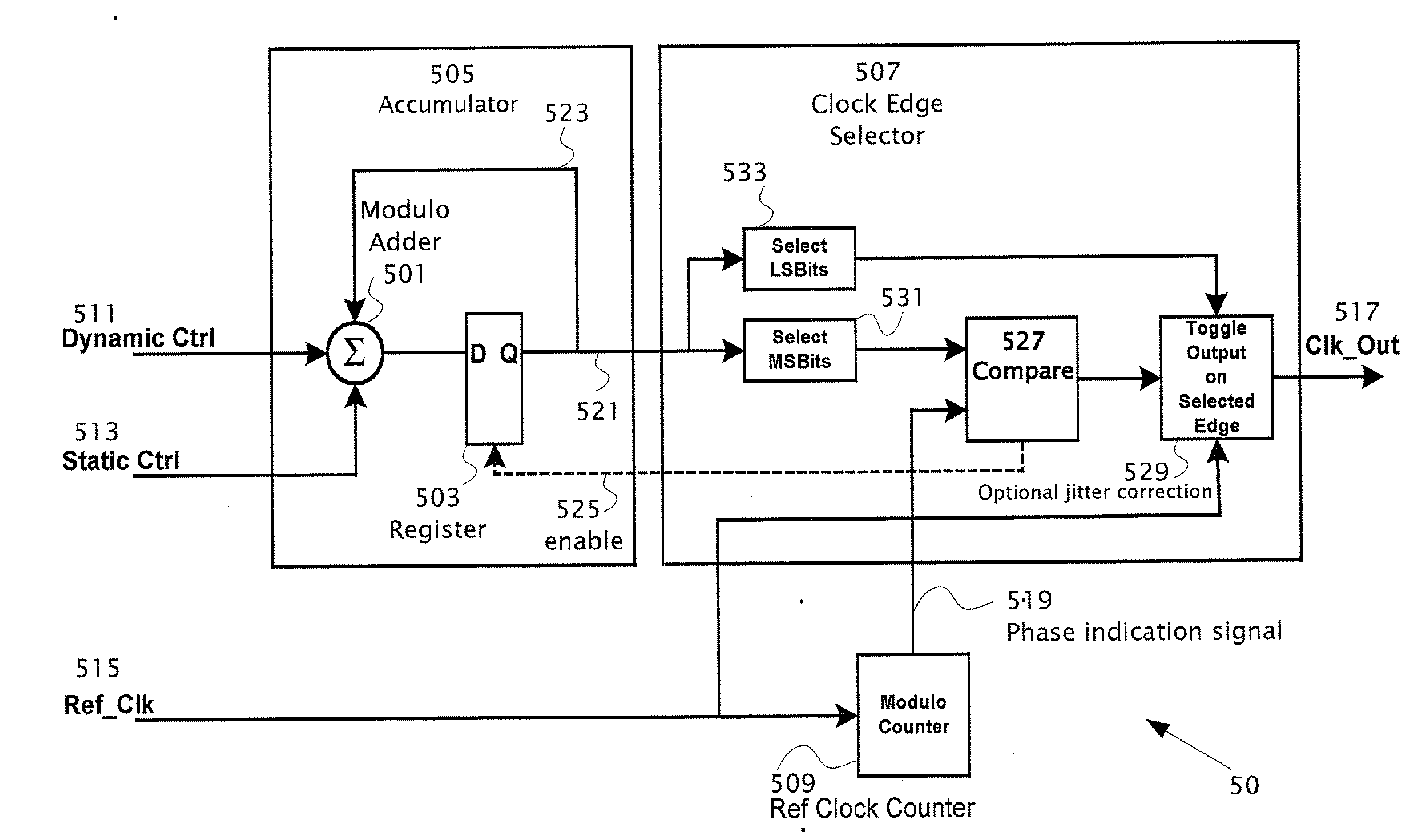
[0037]The present invention is of a circuit and method for generating one or more pulse outputs using a direct digital synthesis circuit with superior operating characteristics. Specifically, pulse output DDS circuit of the present invention is useful for digital devices in which multiple non-related clock signals are required.

[0038]The principles and operation of a system and method for generating one or more pulse outputs using a direct digital synthesis circuit with superior operating characteristics, according to the present invention, may be better understood with reference to the drawings and the accompanying description.

[0039]Before explaining embodiments of the invention in detail, it is to be understood that the invention is not limited in its application to the details of design and the arrangement of the components set forth in the following description or illustrated in the drawings. The invention is capable of other embodiments or of being practiced or carried out in va...


PUM


Abstract

A clock signal generator responsive to a frequency control word and a reference clock signal having a reference clock frequency fref. The clock signal generator generates an output clock signal having a frequency fgen, wherein fgen is less than fref. A modulo-N counter accepts the reference clock signal as input. The modulo-N counter generates a phase-indication signal of the reference clock. The phase indication signal has N clock phases repeating at a frequency of fref / N. An accumulator iteratively accumulates a frequency control word into a modulo-N adder and produces an accumulated value. One or more bits of the accumulated value is fed-back into the modulo-N adder for adding modulo N to the accumulated value in the next iteration. N of the modulo-N adder is the same integer as in the modulo-N counter. A clock edge selector receives as inputs the phase indication signal and one or more bits of the accumulated value and by comparing the inputs selects an edge of the reference clock signal upon which to toggle the state of the output clock signal. The clock edge selector preferably selects the edge from: (i) only rising edges of the reference clock signal, (ii) only falling edges of the reference clock signal or (iii) both rising and falling edges of the reference clock signal. The clock edge selector selects between a rising edge and a falling edge of the reference clock signal preferably based on one or more bits of the accumulated value.

Description

CROSS REFERENCE TO RELATED APPLICATIONS[0001]The present application claims the benefit from U.S. provisional application Ser. No. 60 / 808,791 filed 26 May 2006 by the present inventors.FIELD AND BACKGROUND OF THE INVENTION[0002]The present invention relates to direct digital synthesis (DDS) and particularly to a power and / or speed efficient pulse output DDS circuit. Specifically, the device is used to generate one or more clock signals for digital circuitry whereas the generated clock signals can have frequencies less than but arbitrarily relative to the frequency of the reference clock signal.[0003]In many applications, it is necessary to generate multiple clock signals for clocking of digital circuits that process different streams of data at distinctly and / or subtly different rates. In those applications in which a suitable clock signal is not provided with each data stream, a local clock signal often needs to be generated and recovered from the data stream. An exemplary system t...

Claims


Application Information

Patent Timeline
IPC IPC(8): G06F1/02
CPCG06F1/025
Inventor WARNER, WILLIAM DEANRYAN, RICHARD EDMUND
Owner PMC-SIERRA
Why Eureka
Try Eureka