
Wearable Sensor Device and System

a sensor and wearable technology, applied in the field of continuous sensors, can solve the problems of limb amputation and blindness, enter a comatose state, and serious healthcare complications

Inactive Publication Date: 2007-11-22
LIFESCAN IP HLDG LLC
View PDF17 Cites 486 Cited by
  • Summary
  • Abstract
  • Description
  • Claims
  • Application Information

AI Technical Summary

Benefits of technology

[0023] Having explained that causing the receiver to determine the schedule of wireless transmission from the wearable sensor reduces the power consumption of the overall system, we now explain some further adaptations that either contribute to this aim or contribute to the aim of keeping the wearable sensor as small and lightweight as possible.

Problems solved by technology

Failure to control blood glucose levels within a recommended range can result in serious healthcare complications such as limb amputation and blindness.
Furthermore, failure to accurately measure blood glucose levels may result in hypoglycaemia.
Under such conditions the diabetic patient may initially enter a comatose state, and if untreated may die.
People suffering from diabetes are often at a higher risk of other diseases.
Diabetes also contributes to kidney disease, which occurs when the kidneys do not filter properly and protein leaks into urine in excessive amounts, which eventually can cause kidney failure.
Diabetes is a cause of damage to the retina at the back of the eye and also increases risk of cataracts and glaucoma.
Nerve damage caused by diabetes may interfere with the ability to sense pain and contributes to serious infections.
Because the local controller module is to be worn for 12 hours at a time, it must be relatively lightweight and relatively unsophisticated; most of the detailed analysis of the glucose measurements takes place only in the remote control module.
Again, the patch is relatively unsophisticated and most of the detailed analysis of the glucose measurements takes place only in the remote control module.
Transferring the data to the remote module typically consumes the greater part of the power it is able to supply, which means that the battery life is constrained for the most part by the need to power the RF communication.
This is a particular problem because the local device or skin patch are for the most part out of sight and a low battery level may not immediately be apparent to the user.
The result can be false measurements, or failure to supply measurement data to the remote module, either of which can seriously compromise the welfare of the user, eventually leading in the worst cases to coma and death.
Similar problems arise with the remote module too.
If the batteries in the remote module run low, exactly the same result may ensue.

Method used


Image

  • Wearable Sensor Device and System
  • Wearable Sensor Device and System
  • Wearable Sensor Device and System

Examples


Embodiment Construction

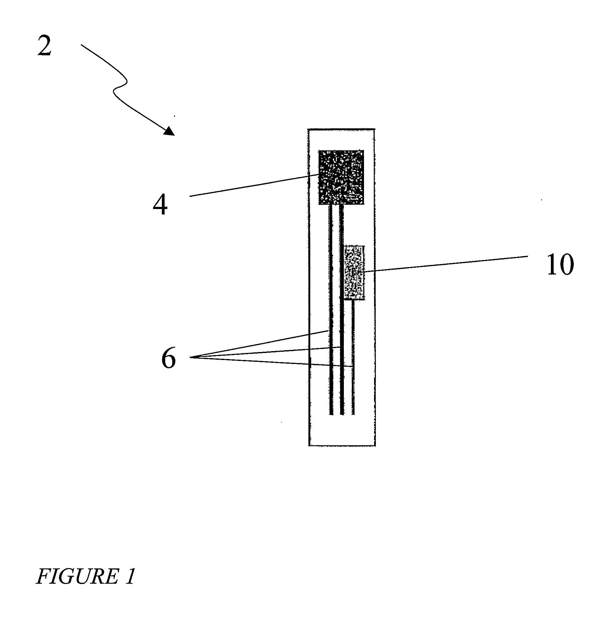
[0054]FIG. 1 shows a test element strip or test strip 2 having a sample area 4, electrical tracks 6, and a Radio Frequency Identification (RFID) tag 10. RFID (Radio Frequency Identification) is a technique which is able to carry data in suitable transponders, generally known as tags, and to retrieve data, by machine-readable means, at a suitable time and place to satisfy particular application needs.

[0055] An example RFID system may have, in addition to at least one tag, a transceiver or means of reading or interrogating the tags and optionally means of communicating the data received from a tag to an information management system. Transceivers are also known as interrogators, readers, or polling devices. Typically the system may also have a facility for entering or programming data into the tags. RFID tags contain an antenna and an integrated circuit. Various configurations of RFID tags are currently available in the marketplace and one such supplier is Texas Instruments® and the ...


PUM


Abstract

A system for determining the level of an analyte in a physiological fluid of a live individual is described. A wearable sensor periodically obtains data representative of the level of the analyte and has a passive RFID tag that stores the data. A receiver wirelessly interrogates the sensor with an RF interrogation signal. The RFID tag modulates or otherwise modifies the wireless interrogation signal using the data and the receiver receives back the modulated or otherwise modified interrogation signal and extracts the data from it. The receiver then determines, from the data, the level of the analyte in the fluid. The sensor may be a photometric or colorimetric sensor or an electrochemical sensor. The receiver may be, or be incorporated into, a hand-held device, a portable device, a PDA, a mobile telephone, or a laptop computer. The resulting system is more versatile and consumes less power than conventional systems.

Description

PRIORITY [0001] This application claims priority benefits under 35 U.S.C. §§ 120 and 371 of International Application PCT / US2005 / 031271 filed on 31 Aug. 2005, which claims priority benefits to U.S. Provisional Application Ser. No. 60 / 606,334 filed on 31 Aug. 2004, which both applications are hereby incorporated by reference in their entireties into this application.FIELD OF THE INVENTION [0002] The invention relates to a continuous sensor for use, in healthcare management, law-enforcement, dope-testing, sanitation or otherwise, for measuring the concentration of any analyte, such as glucose, lactate, urate, alcohol, therapeutic drugs, recreational drugs, performance-enhancing drugs, biomarkers indicative of diseased conditions, hormones, antibodies, metabolites of any of the aforesaid, combinations of any of the aforesaid, other similar indicators or any other analyte in a fluid, especially a physiological fluid such as blood, interstitial fluid (ISF) or urine. Much of the following...

Claims


Application Information

Patent Timeline
Patent Type & Authority Applications(United States)
IPC IPC(8): A61B5/00
CPCA61B5/1411A61B5/14514A61B5/14532A61B5/14865A61B2562/085A61B5/0022A61M5/1723G06F19/3406G06F19/3418G06F19/3456A61K47/48992A61B5/150022A61B5/150068A61B5/150083A61B5/150175A61B5/150358A61B5/150412A61B5/150503A61B5/150526A61B5/150793A61B5/15087A61B5/151A61B5/15186A61B5/155A61B5/157A61K47/6957G16H40/40G16H40/63
Inventor HAYTER, PAUL G.
Owner LIFESCAN IP HLDG LLC
Learn More